


4-88 FI SYSTEM DIAGNOSIS
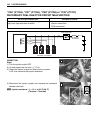
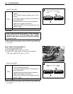
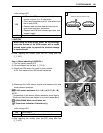
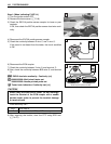
7) Disconnect the ECM coupler.
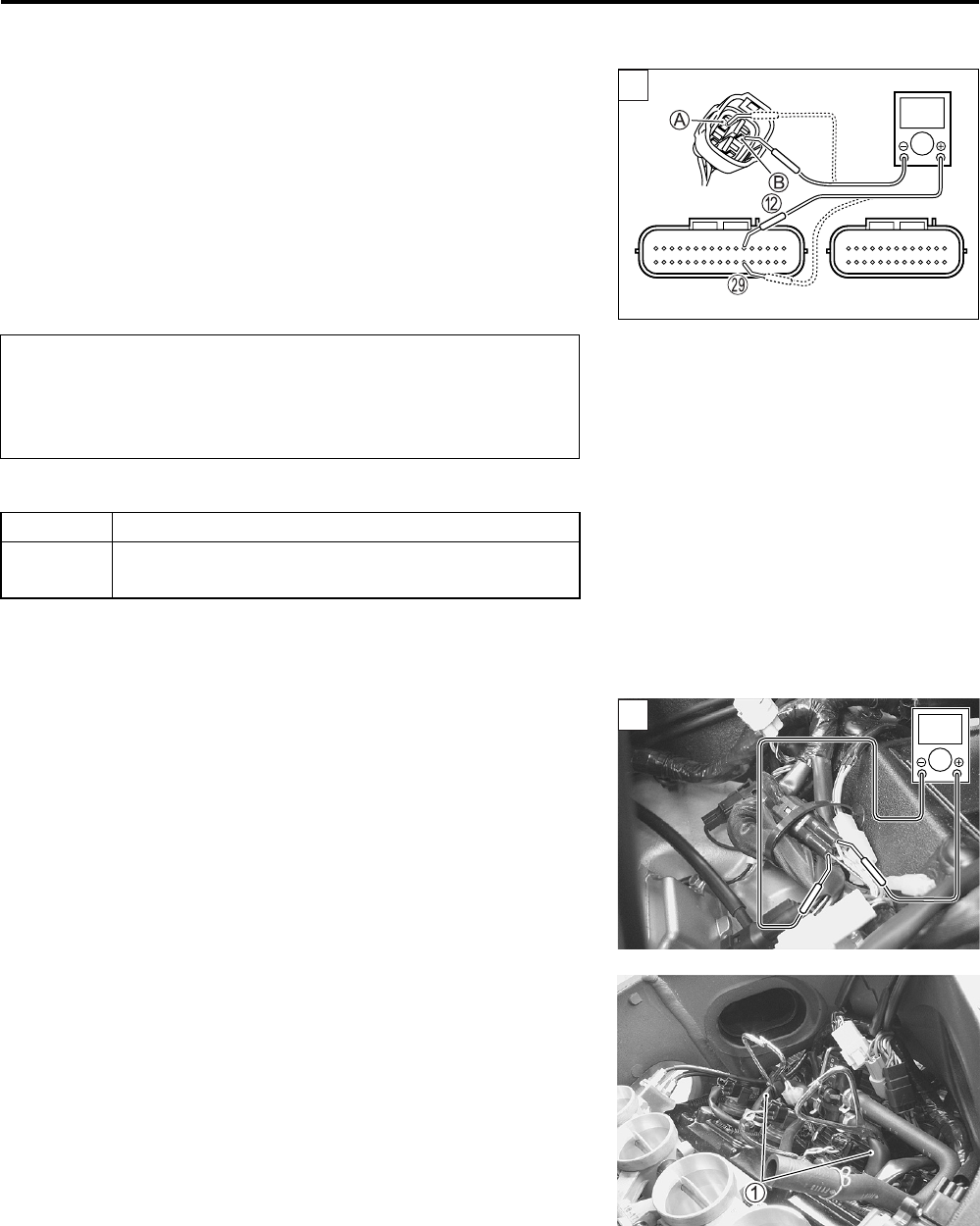
8) Check the continuity between W/G wire A and terminal B.
9) Also, check the continuity between B/Br wire
B
and terminal
S
.
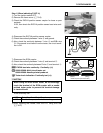
HO2S lead wire continuity:
Continuity ()
09900-25008: Multi-circuit tester set
09900-25009: Needle pointed probe set
Tester knob indication: Continuity test ()
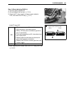
Is the continuity OK?
10)After repairing the trouble, clear the DTC using SDS tool.
(4-27)
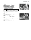
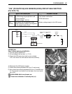
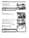
Step 2 (When indicating C44/P0130:)
1) Connect the ECM couplers and HO2 sensor coupler.
2) Warm up the engine enough.
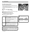
3) Measure the HO2 sensor output voltage between W/G wire
and B/Br wire, when idling condition.
HO2 sensor output voltage at idle speed:
0.4 V and less (+ W/G – - B/Br)
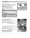
4) If OK, then remove the air cleaner box (5-14) and pinch
the PAIR hoses 1 with proper hose clamps.
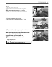
5) Measure the HO2 sensor output voltage while holding the
engine speed at 5 000 r/min.
HO2 sensor output voltage at 5 000 r/min:
0.6 V and more (+ W/G – - B/Br)
09900-25008: Multi-circuit tester set
09900-25009: Needle pointed probe set
Tester knob indication: Voltage ()
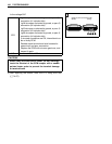
When using the multi-circuit tester, do not storongly
touch the terminal of the ECM coupler with a needle
pointed tester probe to prevent the terminal damage
or terminal bend.
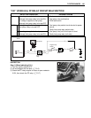
YES Go to Step 2. (When indicating C44/P0130:)
NO
W/G wire shorted to ground, or W/G or B/Br wire
open.
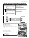
1
!
ECM couplers (Harness side)
2
V