


FI SYSTEM DIAGNOSIS 4-73
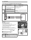
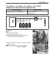
Step 2
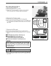
1) Turn the ignition switch OFF.
2) Lift and support the fuel tank. (5-3)
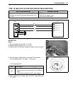
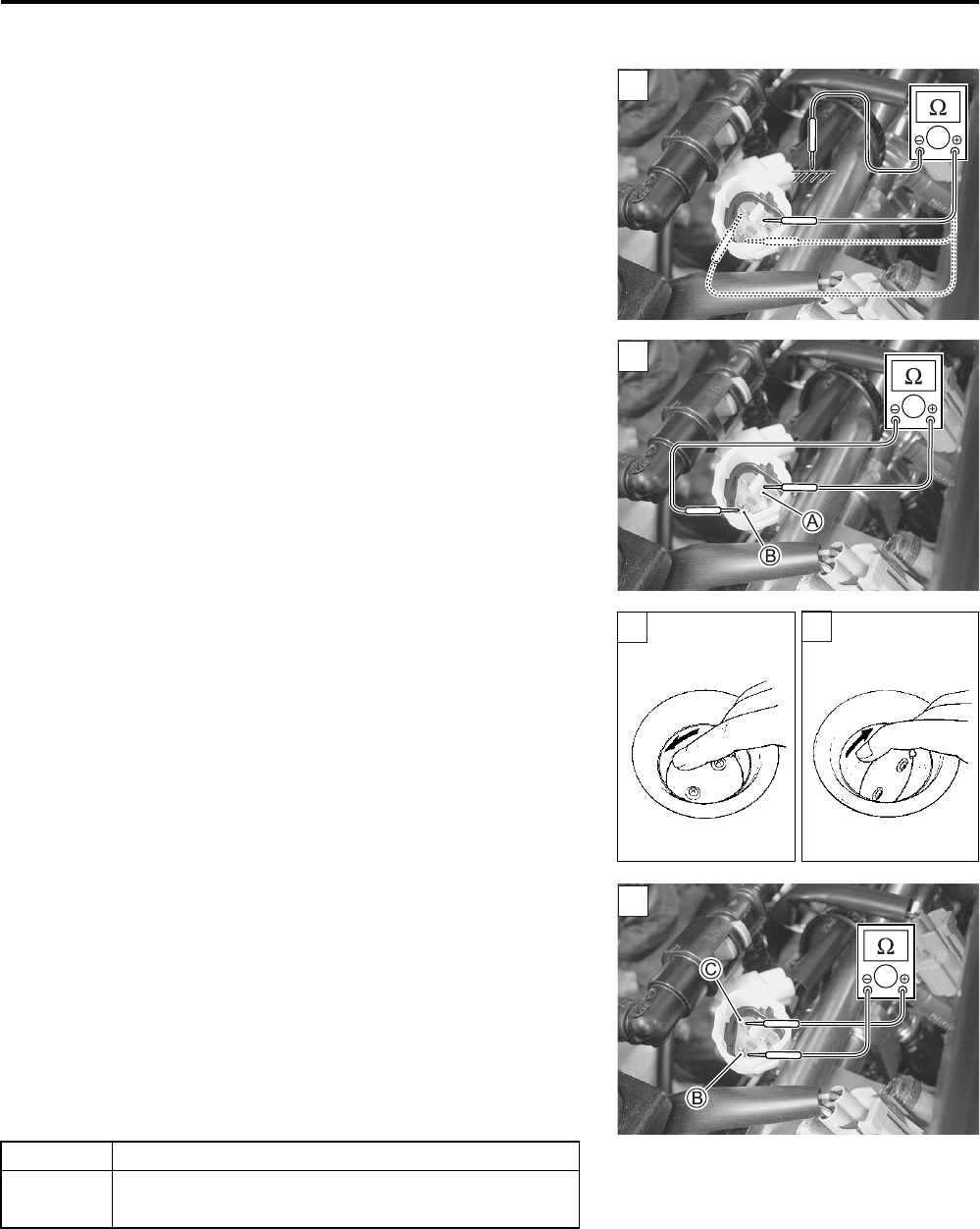
3) Disconnect the STP sensor coupler.
4) Check the continuity between each terminal and ground.
STP sensor continuity: ∞ Ω (Infinity)
(Terminal – Ground)
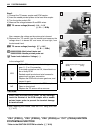
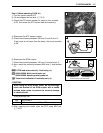
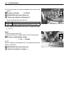
5) If OK, then measure the STP sensor resistance at the wire
terminals (between Y wire A and B wire B).
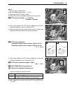
6) Close and open the secondary throttle valve by finger, and
measure the valve closing and opening resistance.
STP sensor resistance
Secondary throttle valve is closed: Approx. 0.5 kΩ
Secondary throttle valve is opened: Approx. 3.9 kΩ
(Y A – B B)
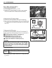
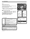
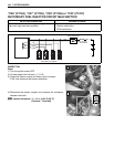
7) If OK, then measure the STP sensor resistance at the wire
terminals (between Bl wire C and B wire B).
STP sensor resistance: Approx. 4.69 kΩ
(Bl c – B B)
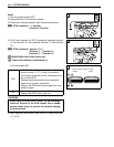
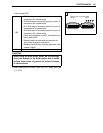
09900-25008: Multi-circuit tester set
Tester knob indication: Resistance (Ω)
Are the continuity and resistance OK?
8) After repairing the trouble, clear the DTC using SDS tool.
(4-27)
2
2
2
2
YES Go to Step 3.
NO
• Reset the STP sensor position correctly.
• Replace the STP sensor with a new one.
2