


8-90 CHASSIS
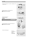
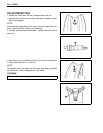
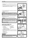
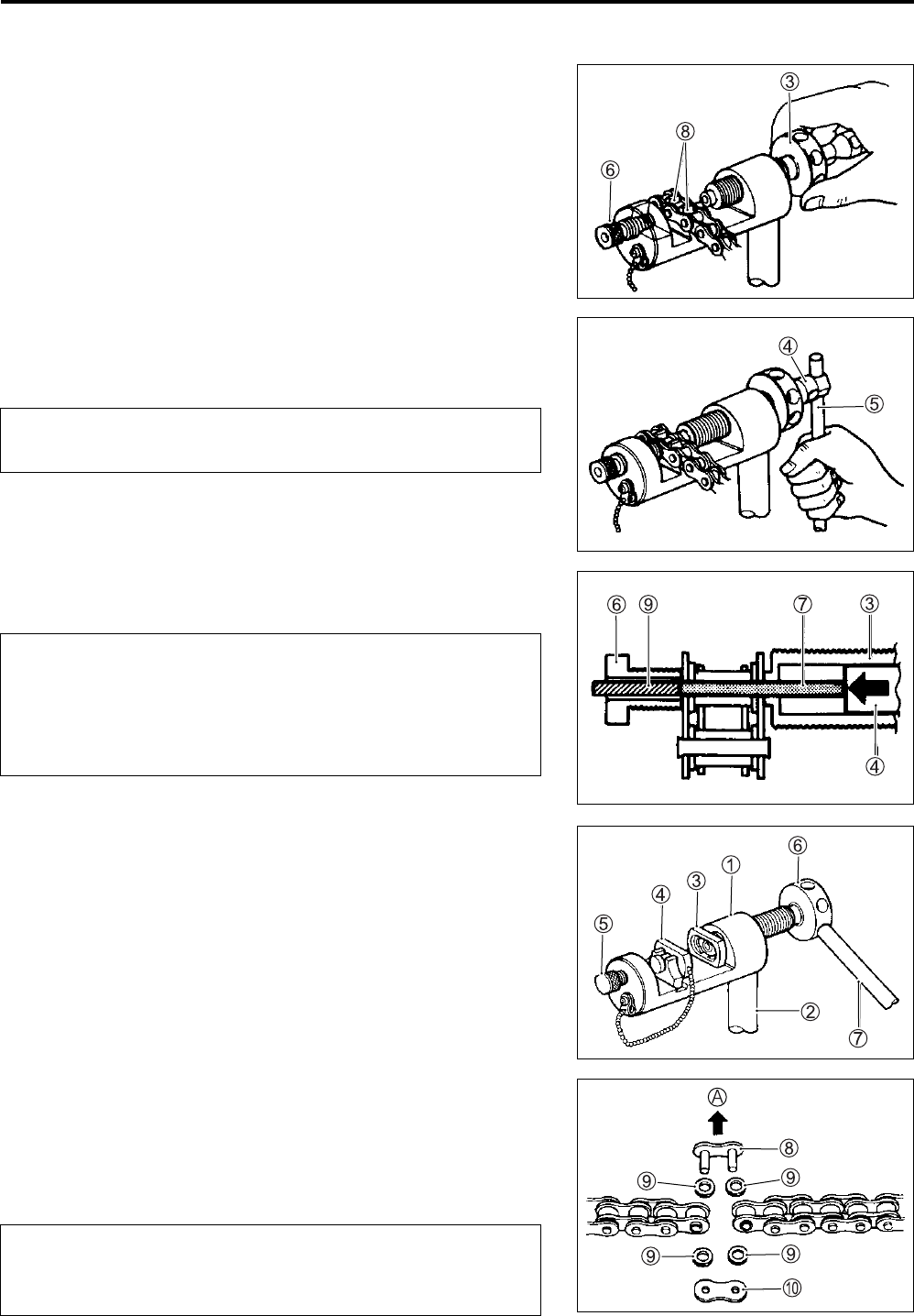
• Place the drive chain link being disjointed on the holder part
8 of the tool.
• Turn in both the adjuster bolt 6 and pressure bolt “A” 3 so
that each of their end hole fits over the chain joint pin properly.
• Tighten the pressure bolt “A” 3 with the bar.
• Turn in the pressure bolt “B” 4 with the bar 5 and force out
the drive chain joint pin 9.
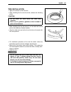
NOTE:
After the joint pin
9
is removed, loosen the pressure bolt “B”
4
and then pressure bolt “A”
3
.
• Remove the joint pin 9 of the other side of joint plate.
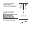
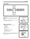
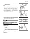
DRIVE CHAIN CONNECTING
JOINT PLATE INSTALLATION
• Set up the special tool as shown in the illustration.
1 Tool body 5 Adjuster bolt
2 Grip handle (without hole)
3 Joint plate holder 6 Pressure bolt “A”
(engraved mark “C520”) 7 Bar
4 Wedge holder & wedge pin
• Connect both ends of the drive chain with the joint pin 8
inserted from the wheel side A as installed on the motorcycle.
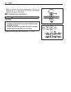
9 O-ring … 4 pcs.
0 Joint plate
Joint set part number
RK: 27620-06G00
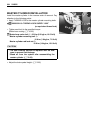
Continue turning in the pressure bolt “B” 4 until the
joint pin has been completely pushed out of the chain.
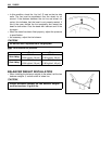
Never reuse joint pins, O-rings and plates. After joint
pins, O-rings and plates have been removed from the
drive chain, the removed joint pins, O-rings and plates
should be discarded and new joint plate, O-rings and
plate must be installed.
Do not use joint clip type of drive chain. The joint clip
may have a chance to drop which may cause severe
damage to motorcycle and severe injury.
(C520)