


FI SYSTEM DIAGNOSIS 4-45
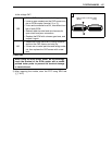
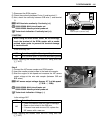
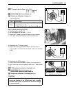
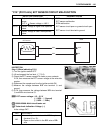
TP sensor input voltage: 4.5 – 5.5 V
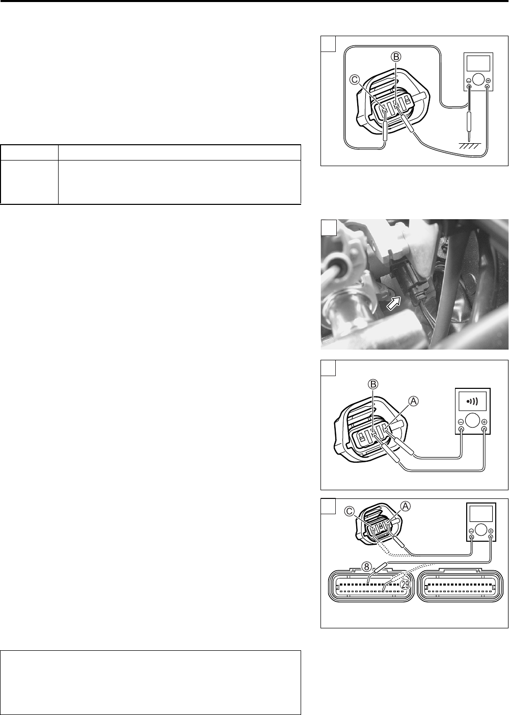
(+ R – - Ground)
(+ R – - B/Br)
09900-25008: Multi-circuit tester set
Tester knob indication: Voltage ()
Is the voltage OK?
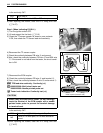
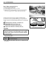
Step 1 (When indicating P0120-H:)
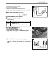
1) Turn the ignition switch OFF.
2) Lift and support the fuel tank. (5-3)
3) Check the TP sensor coupler for loose or poor contacts.
If OK, then check the TP sensor lead wire continuity.
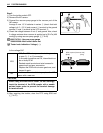
4) Disconnect the TP sensor coupler.
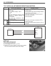
5) Check the continuity between P/B wire A and R wire B.
If the sound is not heard from the tester, the circuit condition
is OK.
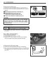
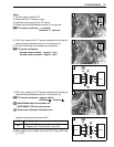
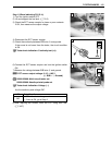
6) Disconnect the ECM coupler.
7) Check the continuity between P/B wire A and terminal 8.
8) Also, check the continuity between B/Br wire C and terminal
S.
TPS lead wire continuity: Continuity ( )
09900-25008: Multi-circuit tester set
09900-25009: Needle pointed probe set
Tester knob indication: Continuity test ()
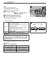
YES Go to Step 2.
NO
• Loose or poor contacts on the ECM coupler
(terminal A or S).
• Open or short circuit in the R wire or B/Br wire.
1
V
1
1
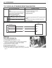
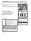
When using the multi-circuit tester, do not storongly
touch the terminal of the ECM coupler with a needle
pointed tester probe to prevent the terminal damage
or terminal bend.
1
!
(Black)
(Gray)
ECM couplers (Harness side)