


FI SYSTEM DIAGNOSIS 4-7
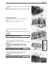
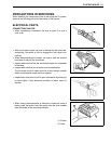
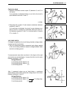
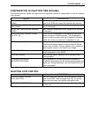
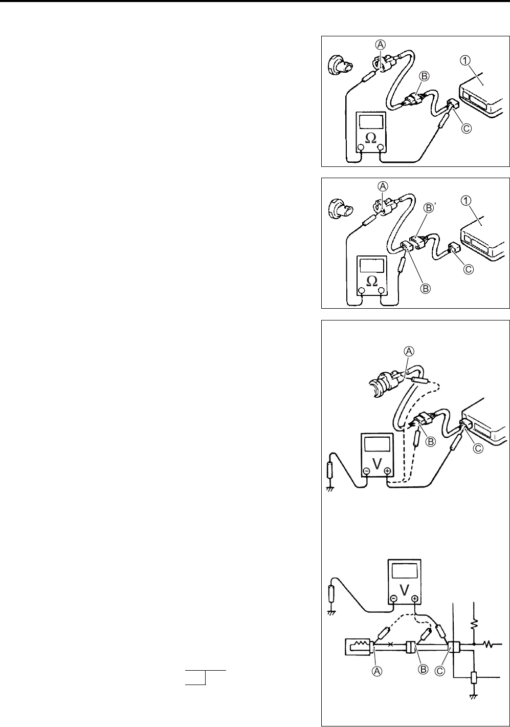
Continuity check
• Measure resistance across coupler B (between A and C in
the figure).
If no continuity is indicated (infinity or over limit), the circuit is
open between terminals A and C.
1 ECM
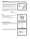
• Disconnect the coupler B and measure resistance between
couplers A and B.
If no continuity is indicated, the circuit is open between cou-
plers A and B. If continuity is indicated, there is an open cir-
cuit between couplers B’ and C or an abnormality in coupler
B’ or coupler C.
1 ECM
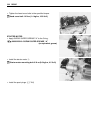
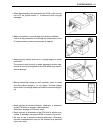
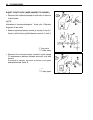
VOLTAGE CHECK
If voltage is supplied to the circuit being checked, voltage check
can be used as circuit check.
• With all connectors/couplers connected and voltage applied
to the circuit being checked, measure voltage between each
terminal and body ground.
If measurements were taken as shown in the figure at the right
and results are as listed below, it means that the circuit is open
between terminals A and B.
Voltage Between:
C and body ground: Approx. 5 V
B and body ground: Approx. 5 V
A and body ground: 0 V
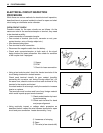
Also, if measured values are as listed below, a resistance
(abnormality) exists which causes the voltage drop in the circuit
between terminals A and B.
Voltage Between:
C and body ground:
Approx. 5 V
B and body ground:
Approx. 5 V
2 V voltage drop
A and body ground:
3 V
5 V
0 V
5 V
5 V