


FI SYSTEM DIAGNOSIS 4-63
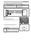
“C23” (P1651-H/L) TO SENSOR CIRCUIT MALFUNCTION
INSPECTION
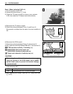
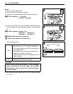
Step 1 (When indicating C23:)
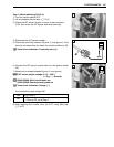
1) Turn the ignition switch OFF.
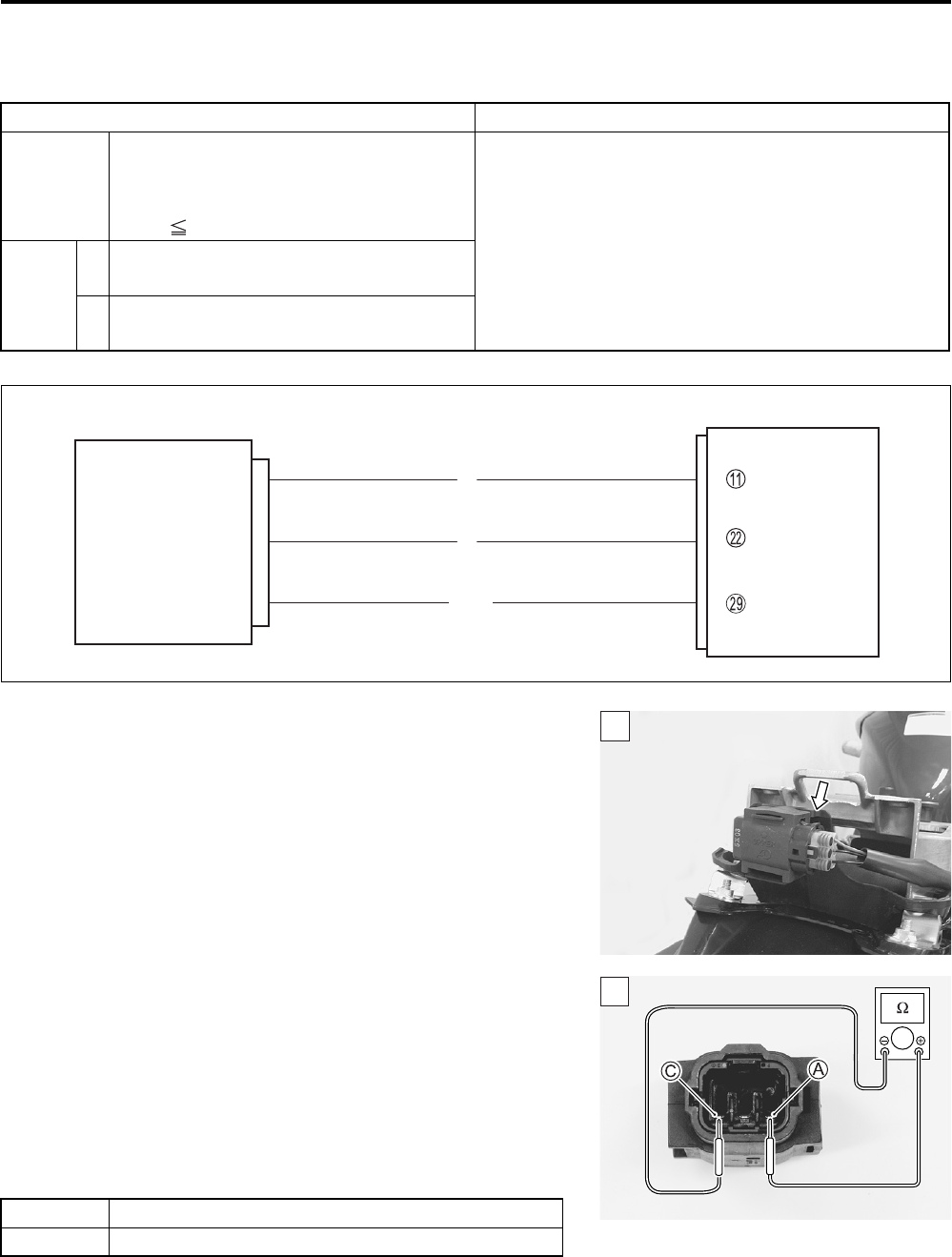
2) Remove the frame cover. (8-8)
3) Check the TO sensor coupler for loose or poor contacts.
If OK, then measure the TO sensor resistance.
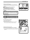
4) Disconnect the TO sensor coupler.
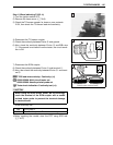
5) Measure the resistance between terminal A and terminal C.
TO sensor resistance: 16.5 – 22.3 kΩ
(Terminal A – Terminal C)
09900-25008: Multi-circuit tester set
Tester knob indication: Resistance (Ω)
Is the resistance OK?
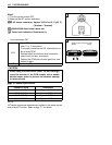
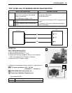
DETECTED CONDITION POSSIBLE CAUSE
C23 The sensor voltage should be the follow-
ing for 2 sec. and more, after ignition
switch is turned ON.
0.2 V Sensor voltage < 4.8 V
• TO sensor circuit open or short
• TO sensor malfunction
• ECM malfunction
P1651
H
Sensor voltage is higher than specified
value.
• TO sensor circuit shorted to VCC or ground circuit
open
• TO sensor circuit open or shorted to ground or
VCC circuit open
L
Sensor voltage is lower than specified
value.
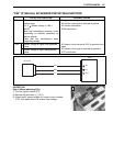
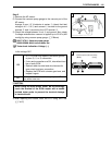
ECM
E2
TOS
R
B/Br
VCC
TO sensor
B
1
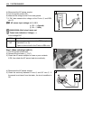
YES Go to Step 2.
NO Replace the TO sensor with a new one.
1