6-8 EXHAUST SYSTEM
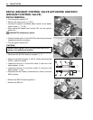
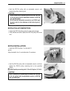
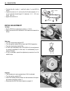
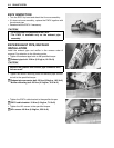
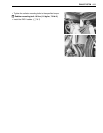
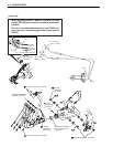
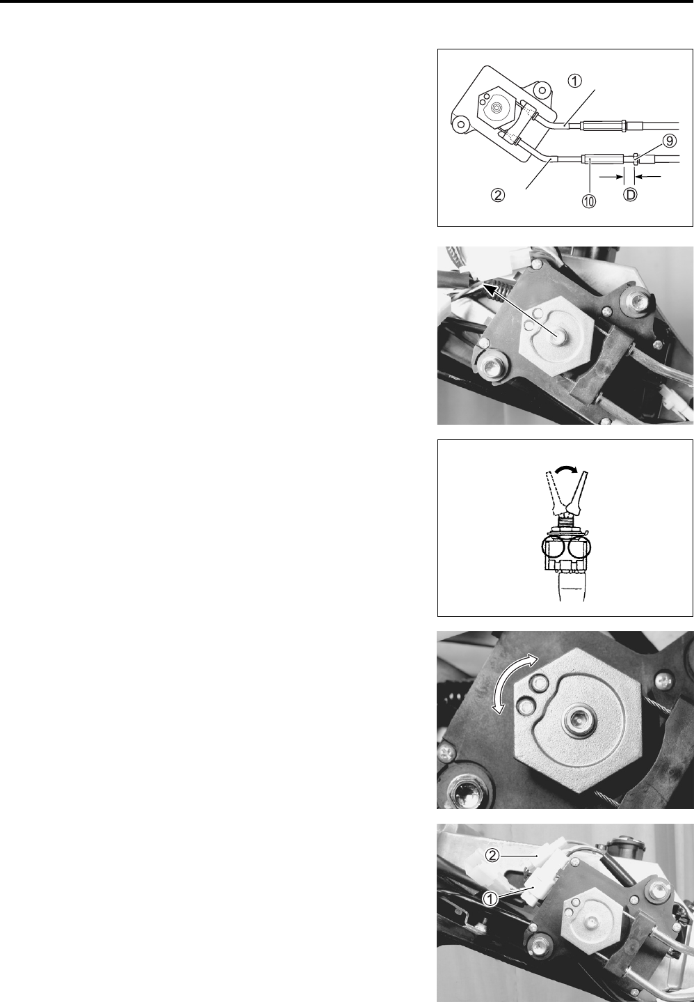
• Connect the No.1 cable 1 and No.2 cable 2 to the EXCVA
pulley.
• Loosen the lock-nut 9 and turn the No.2 cable adjuster 0 in
or out until the thread length D becomes 11.0 – 12.0 mm
(0.43 – 0.47 in).
• tighten the lock-nut 9.
EXCVA ADJUSTMENT
1st step:
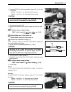
• Set the EXCVA to adjustment position. (6-4)
• Make sure that the No.1cable and No.2 cable are fixed with a
clamp.
2nd step:
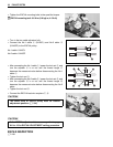
• Turn the mode select switch OFF.
• Turn the ignition switch ON to check the EXCVA operation.
• Turn the mode select switch ON.
• If C46 is not indicated on the LCD (DISPLAY), the adjustment
is correctly completed. In this case, it is unnecessary to pro-
ceed to 3rd step.
• If C46 is indicated, repeat the adjustment procedure from 3rd
and 4th step.
3rd step:
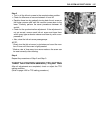
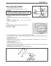
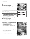
• This procedure is only required when C46 is indicated.
• Turn the ignition switch OFF.
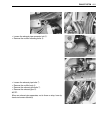
• Insert the needle pointed probes into the backside of the posi-
tion sensor lead wire coupler 1.
• Disconnect the EXCVA motor lead wire coupler 2.
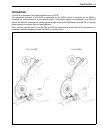
No. 1 cable
No. 2 cable
ON
OFF


