


CHASSIS 8-91
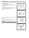
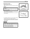
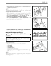
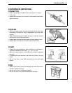
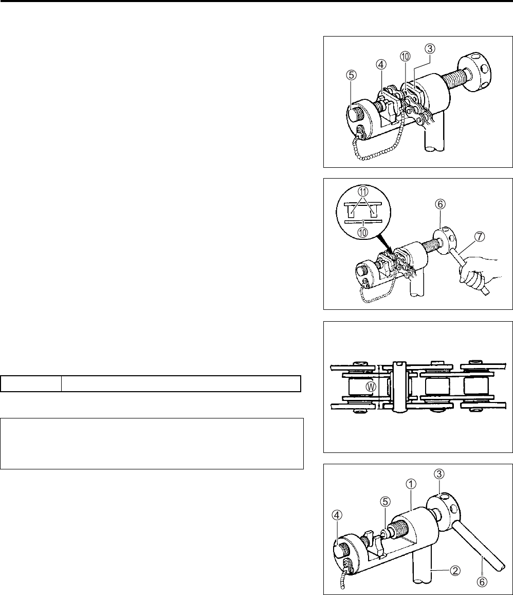
• Apply grease on the recessed portion of the joint plate holder
3 and set the joint plate 0.
NOTE:
When positioning the joint plate
0
on the tool, its stamp mark
must face the joint plate holder
3
side.
• Set the drive chain on the tool as illustrated and turn in the
adjuster bolt 5 to secure the wedge holder & wedge pin 4.
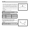
• Turn in the pressure bolt “A” 6 and align two joint pins A
properly with the respective holes of the joint plate 0
• Turn in the pressure bolt “A” 6 further using the bar 7 to
press the joint plate over the joint pins.
• Continue pressing the joint plate until the distance between
the two joint plates come to the specification.
Joint plate distance specification W
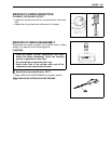
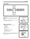
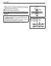
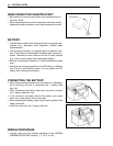
JOINT PIN STAKING
• Set up the special tool as shown in the illustration.
1 Tool body
2 Grip handle
3 Pressure bolt “A”
4 Adjuster bolt (without hole)
5 Staking pin (stowed inside grip handle behind rubber cap)
6 Bar
NOTE:
Before staking the joint pin, apply a small quantity of grease to
the staking pin
5
.
RK 18.6 – 18.9 mm (0.732 – 0.744 in)
Should pressing of the joint plate be made excessively
beyond the specified dimension, the work should be
redone using the new joint parts.