


FI SYSTEM DIAGNOSIS 4-59
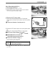
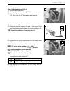
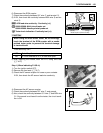
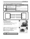
6) Disconnect the ECM coupler.
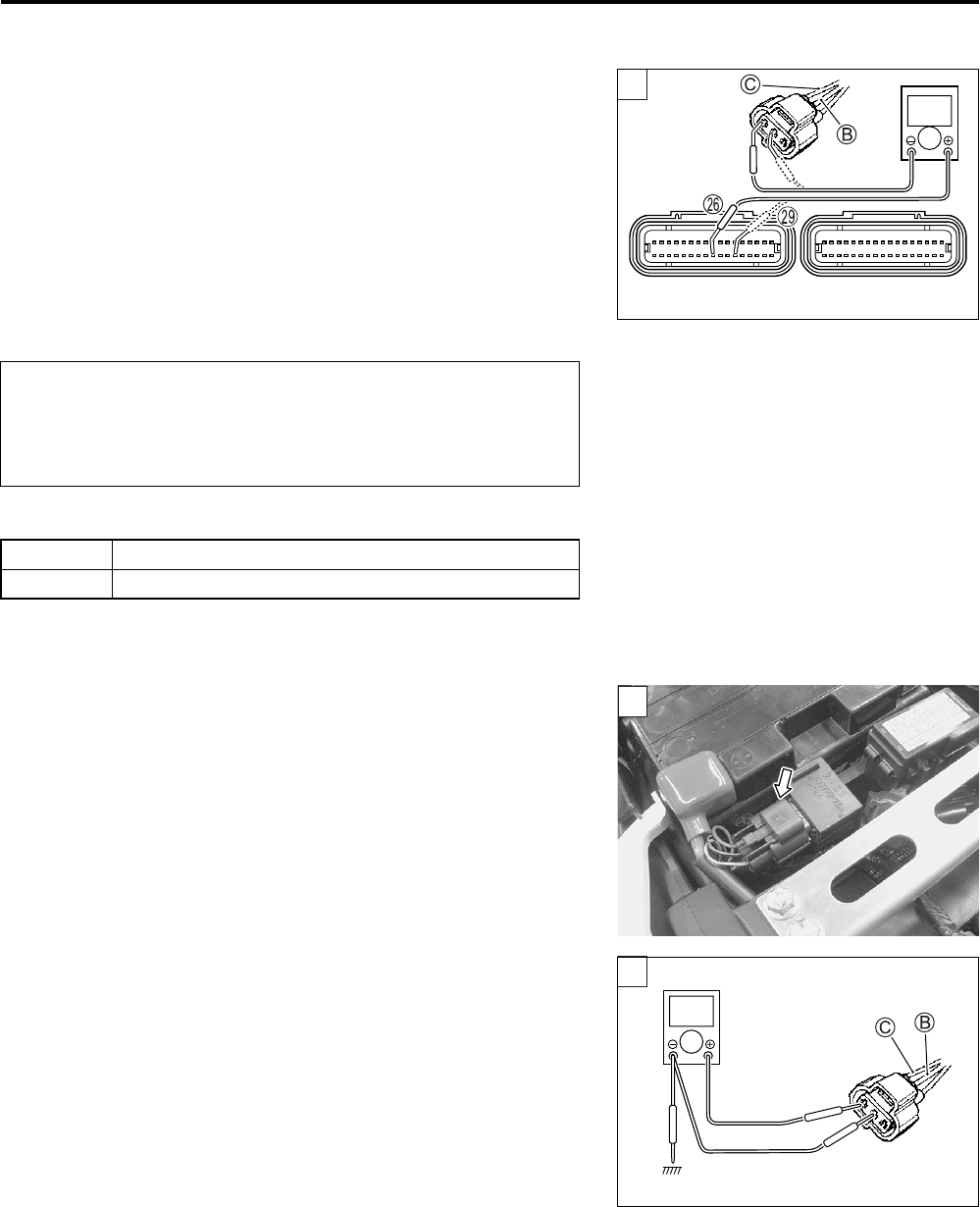
7) Check the continuity between G/Y wire C and terminal P.
8) If OK, then check the continuity between B/Br wire B and ter-
minal S.
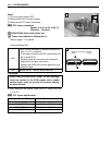
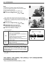
APS lead wire continuity:
Continuity ()
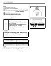
09900-25008: Multi-circuit tester set
09900-25009: Needle pointed probe set
Tester knob indication: Continuity test ()
Is the continuity OK?
9) After repairing the trouble, clear the DTC using SDS tool.
(4-27)
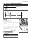
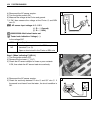
Step 1 (When indicating P1450-L:)
1) Turn the ignition switch OFF.
2) Remove the front seat. (8-7)
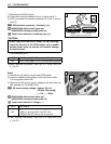
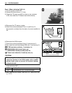
3) Check the AP sensor coupler for loose or poor contacts.
If OK, then check the AP sensor lead wire continuity.
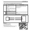
4) Disconnect the AP sensor coupler.
5) Check the continuity between G/Y wire C and ground.
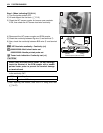
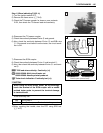
6) Also, check the continuity between G/Y wire C and B/Br wire
B. If the sound is not heard from the tester, the circuit condi-
tion is OK.
When using the multi-circuit tester, do not storongly
touch the terminal of the ECM coupler with a needle
pointed tester probe to prevent the terminal damage
or terminal bend.
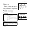
YES Go to Step 2.
NO G/Y wire shorted to VCC, or B/Br wire open
1
!
(Black)
(Gray)
ECM couplers (Harness side)
1
V
1