


10-2 SERVICING INFORMATION
TROUBLESHOOTING
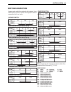
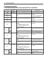
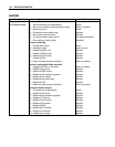
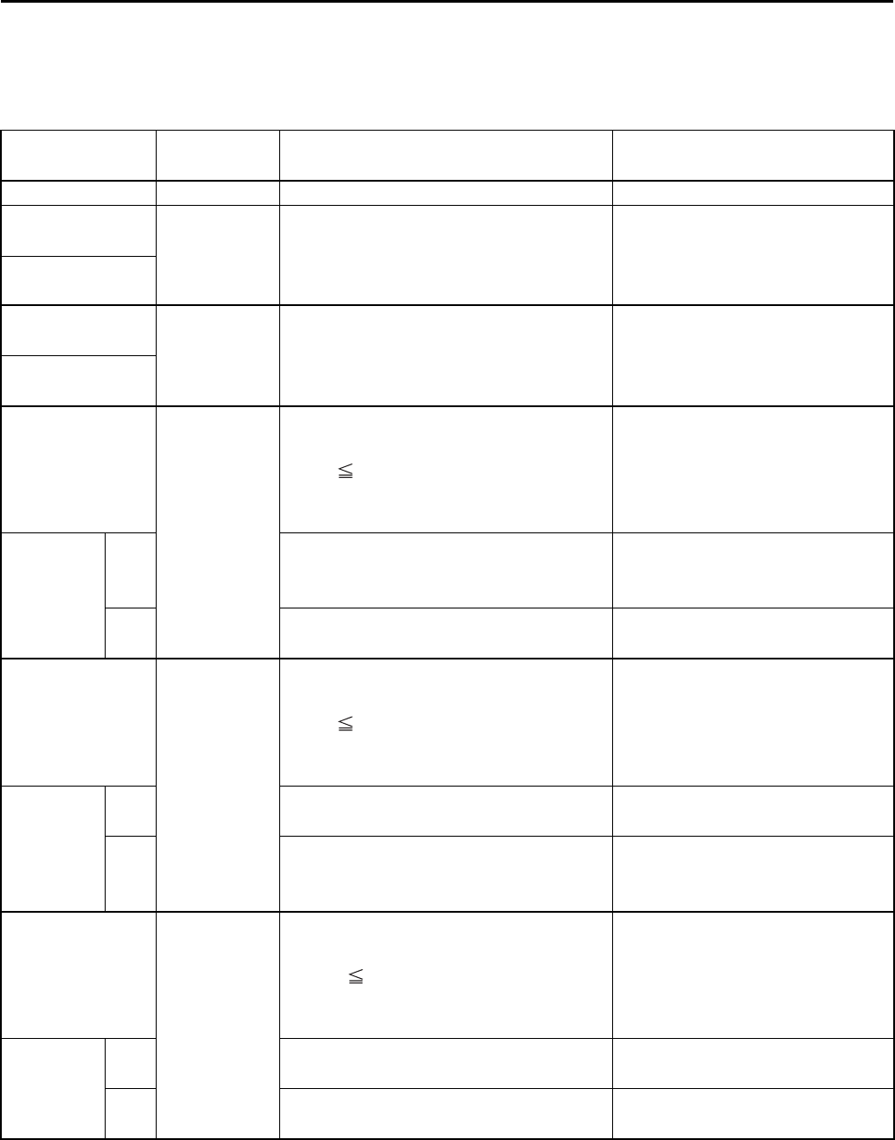
FI SYSTEM MALFUNCTION CODE AND DEFECTIVE CONDITION
DTC No.
DETECTED
ITEM
DETECTED FAILURE CONDITION CHECK FOR
C00 NO FAULT
––––––––––– –––––––––––
C11
CMP sensor The signal does not reach ECM for 3
sec. or more, after receiving the starter
signal.
CMP sensor wiring and mechan-
ical parts
CMP sensor, intake cam pin,
wiring/coupler connection
P0340
C12
CKP sensor The signal does not reach ECM for 3
sec. or more, after receiving the starter
signal.
CKP sensor wiring and mechan-
ical parts
CKP sensor, lead wire/coupler
connection
P0335
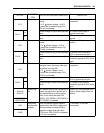
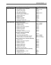
C13
IAP sensor The sensor should produce following
voltage.
0.5 V sensor voltage < 4.85 V
In other than the above range, C13
(P0105) is indicated.
IAP sensor, lead wire/coupler
connection
P0105
H
Sensor voltage is higher than specified
value.
IAP sensor circuit open or
shorted to VCC or ground circuit
open
L
Sensor voltage is lower than specified
value.
IAP sensor circuit shorted to
ground or VCC circuit open
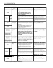
C14
TP sensor The sensor should produce following
voltage.
0.2 V sensor voltage < 4.80 V
In other than the above range, C14
(P0120) is indicated.
TP sensor, lead wire/coupler
connection
P0120
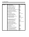
H
Sensor voltage is higher than specified
value.
TP sensor circuit shorted to
VCC or ground circuit open
L
Sensor voltage is lower than specified
value.
TP sensor circuit open or
shorted to ground or VCC circuit
open
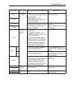
C15
ECT sensor The sensor voltage should be the fol-
lowing.
0.15 V sensor voltage < 4.85 V
In other than the above range, C15
(P0115) is indicated.
ECT sensor, lead wire/coupler
connection
P0115
H
Sensor voltage is higher than specified
value.
ECT sensor circuit open or
ground circuit open
L
Sensor voltage is lower than specified
value.
ECT sensor circuit shorted to
ground