


4-14 FI SYSTEM DIAGNOSIS
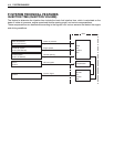
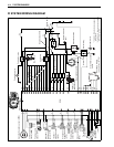
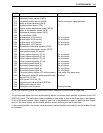
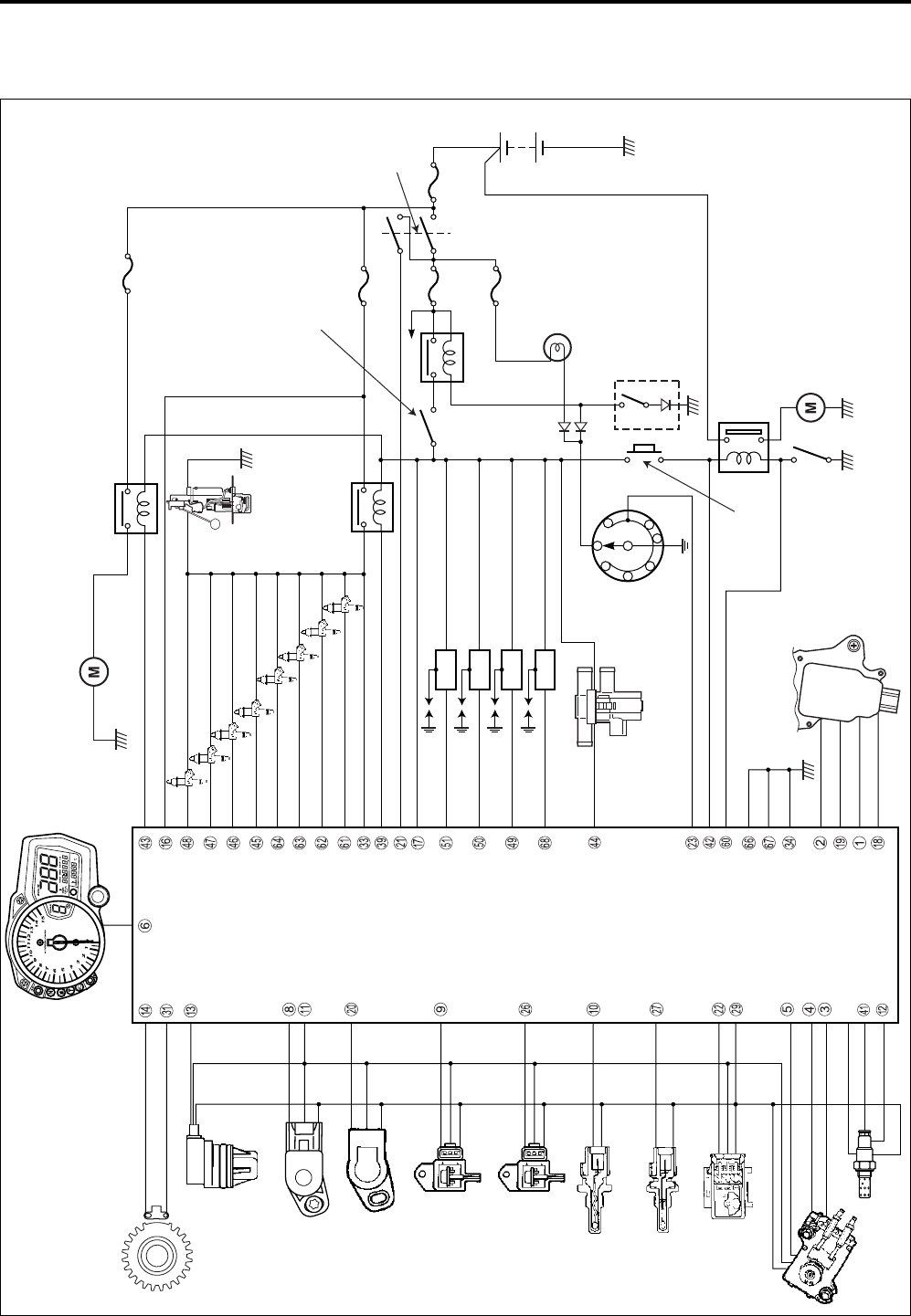
FI SYSTEM WIRING DIAGRAM
10 A
10 A 30 A
15 A
Speedometer
Camshaft position
sensor (CMPS)
Crankshaft position sensor (CKPS)
Throttle position
sensor (TPS)
Intake air
pressure sensor
(IAPS)
Atmospheric
pressure sensor
(APS)
Engine coolant temperature
sensor (ECTS)
Intake air temperature sensor
(IATS)
Tip-over
sensor (TOS)
Secondary throttle
valve actuator (STVA)
Clutch lever position
switch
Starter motor
Starter relay
Side-stand switch
Side-stand
relay
Engine stop switch
Fuel pump
relay
Fuel pump
Primary
fuel injector
Ignition coil (IG COIL)
Ignition switch
Neutral indicator
light
Starter switch
Gear position switch
N
61
5
42
3
ECM
Secondary
throttle position
sensor (STPS)
EXCVA
Secondary
fuel injector
Cooling fan motor
15 A
*1 For E-02, 19 markets are equipped
HO2 sensor.
*2
PAIR control
solenoid valve
HO2 sensor
W/B
W/G
*1
Cooling fan relay
O/W
*2 For E-02, 19, 24 markets are equipped
immobilizer system.
B/G
B/Y
G/W
O/BI
P/B
Y/W
G/B
G/Y
B/BI
Dg
B
B/Br
B/R
R/B
G
W/B
B/Lg
P/W
B/W
B/W
B/W
B/Y
Y/G
W/G
G
Y
B
W/BI
O/Y
Y/B
Y/R
Lg/BI
Lg/G
Lg/W
Lg
Gr/R
Gr/Y
Gr/B
Gr/W
R/BI
O/R
O/G (E-02, 19, 24) O/W (E-03, 28, 33)
P
Y
R
#1
#1
#1
#2
#2
#2
#3
#3
#3
#4
#4
#4