


4-92 FI SYSTEM DIAGNOSIS
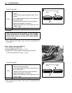
Step 1 (When indicating P1657-H:)
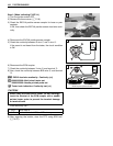
1) Turn the ignition switch OFF.
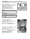
2) Remove the frame cover. (5-8)
3) Check the EXCVA position sensor coupler for loose or poor
contacts.
If OK, then check the EXCVA position sensor lead wire conti-
nuity.
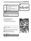
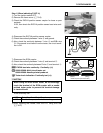
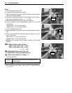
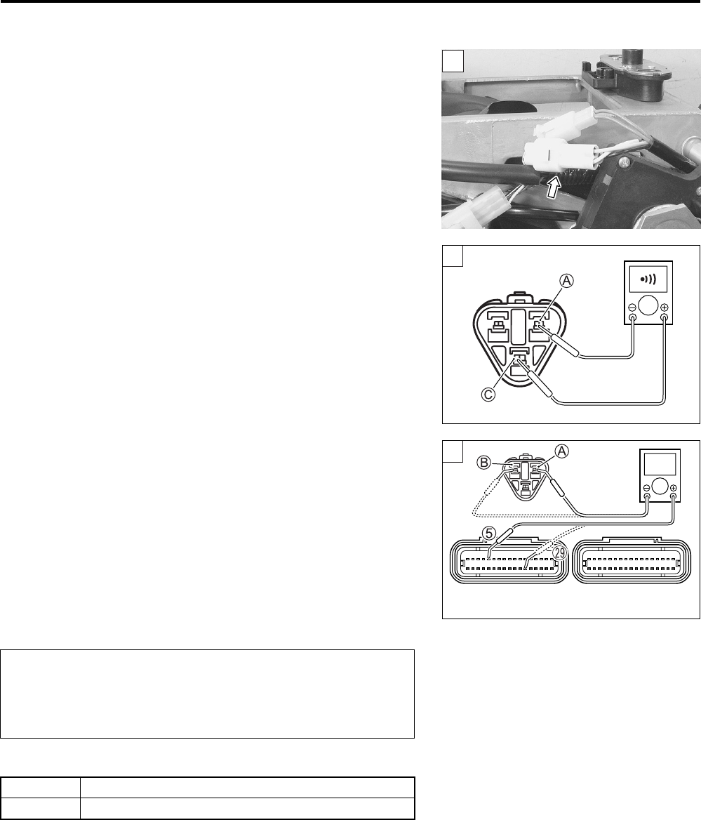
4) Disconnect the EXCVA position sensor coupler.
5) Check the continuity between R wire C and Y wire A.
If the sound is not heard from the tester, the circuit condition
is OK.
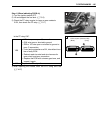
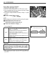
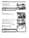
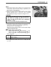
6) Disconnect the ECM coupler.
7) Check the continuity between Y wire A and terminal 5.
8) Also, check the continuity between B/Br wire B and terminal
S.
EXCVA lead wire continuity:
Continuity ()
09900-25008: Multi-circuit tester set
09900-25009: Needle pointed probe set
Tester knob indication: Continuity test ()
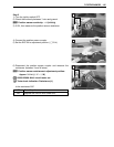
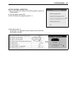
Is the continuity OK?
9) After repairing the trouble, clear the DTC using SDS tool.
(4-27)
1
1
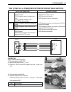
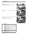
When using the multi-circuit tester, do not storongly
touch the terminal of the ECM coupler with a needle
pointed tester probe to prevent the terminal damage
or terminal bend.
YES Go to Step 4.
NO Y wire shorted to VCC, or B/Br wire open
1
!
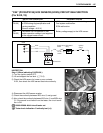
ECM couplers (Harness side)
(Black)
(Gray)