


4-56 FI SYSTEM DIAGNOSIS
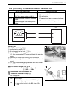
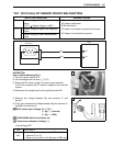
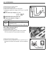
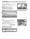
Step 2
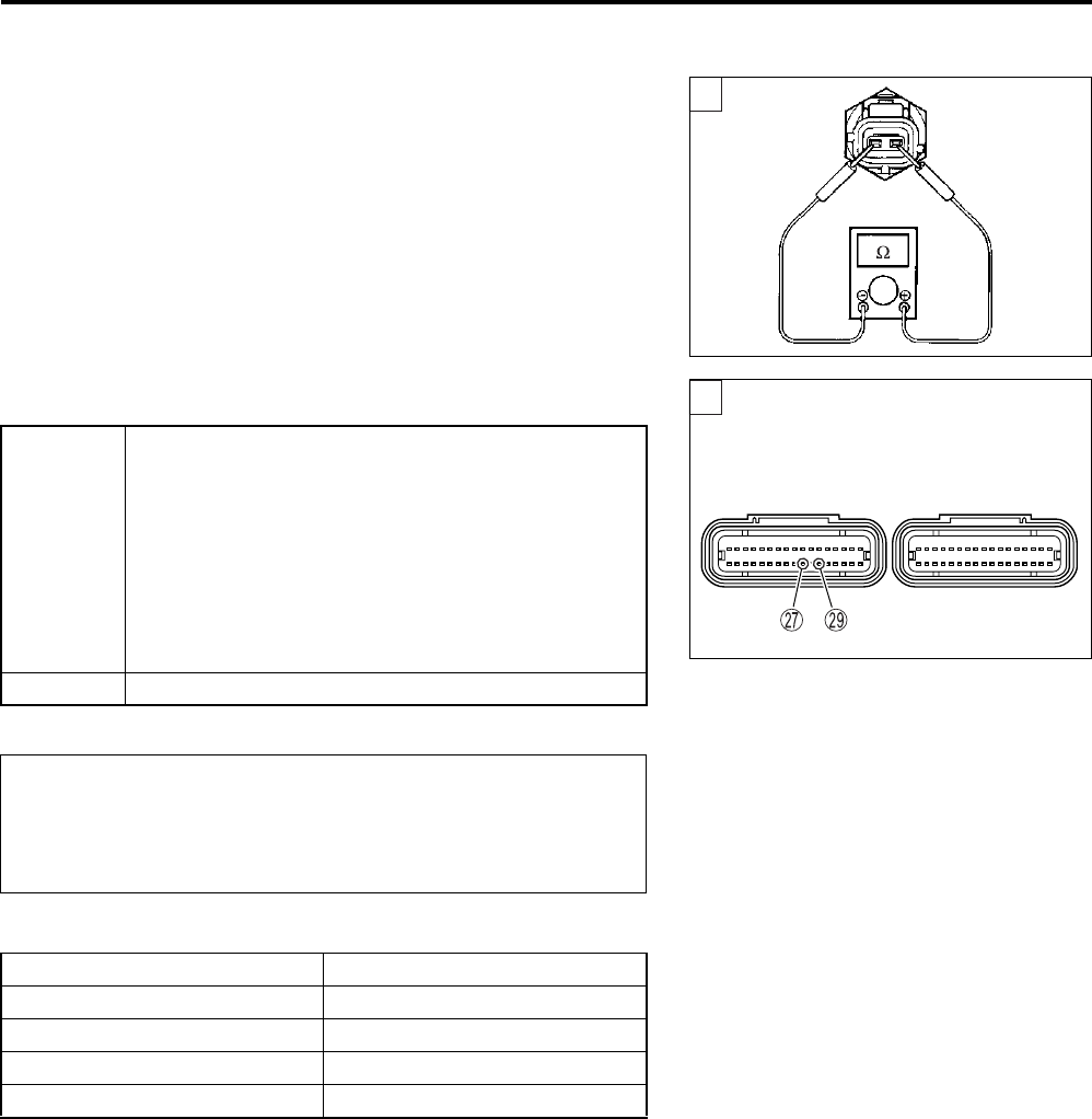
1) Turn the ignition switch OFF.
2) Measure the IAT sensor resistance.
IAT sensor resistance: Approx. 2.45 k
Ω
at 20 °C (68 °F)
(Terminal – Terminal)
09900-25008: Multi-circuit tester set
Tester knob indication: Resistance (Ω)
Is the resistance OK?
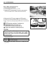
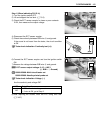
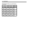
IAT sensor specification
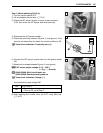
NOTE:
IAT sensor resistance measurement method is the same way as
that of the ECT sensor. Refer to page 7-7 for details.
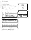
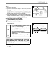
2
YES
• Dg or B/Br wire open or shorted to ground, or
poor Q or S connection
• If wire and connection are OK, intermittent trou-
ble or faulty ECM.
• Recheck each terminal and wire harness for
open circuit and poor connection.
• Replace the ECM with a known good one, and
inspect it again.
NO Replace the IAT sensor with a new one.
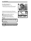
When using the multi-circuit tester, do not storongly
touch the terminal of the ECM coupler with a needle
pointed tester probe to prevent the terminal damage
or terminal bend.
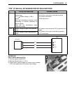
Intake Air Temp Resistance
20 °C (68 °F) Approx. 2.45 kΩ
50 °C (122 °F) Approx. 0.808 kΩ
80 °C (176 °F) Approx. 0.322 kΩ
110 °C (230 °F) Approx. 0.148 kΩ
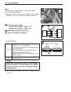
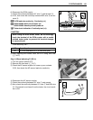
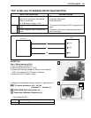
2
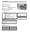
(Black) (Gray)
ECM couplers (Harness side)