


FI SYSTEM DIAGNOSIS 4-61
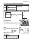
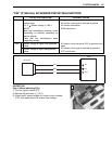
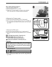
Step 3
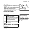
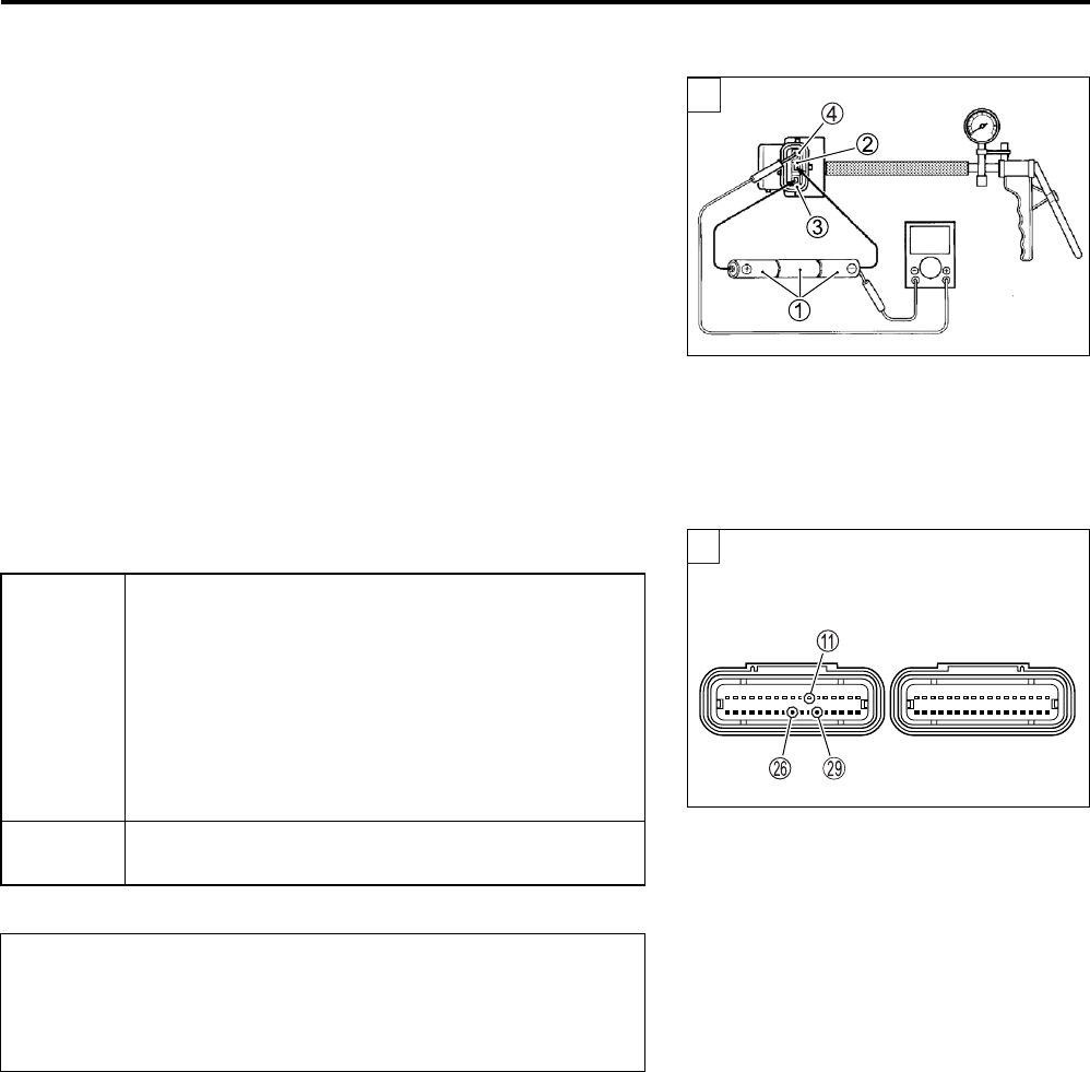
1) Remove the AP sensor.
2) Connect the vacuum pump gauge to the vacuum port of the
AP sensor.
Arrange 3 new 1.5 V batteries in series 1 (check that total
voltage is 4.5 – 5.0 V) and connect - terminal to the ground
terminal 2 and + terminal to the VCC terminal 3.
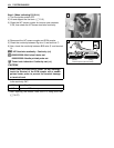
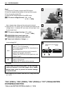
3) Check the voltage between V-out 4 and ground. Also, check
if voltage reduces when vacuum is applied up to 53 kPa (400
mmHg) by using vacuum pump gauge. (Below)
09917-47011: Vacuum pump gauge
09900-25008: Multi-circuit tester set
Tester knob indication: Voltage ()
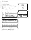
Is the voltage OK?
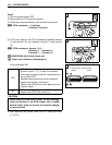
4) After repairing the trouble, clear the DTC using SDS tool.
(4-27)
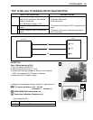
YES
• G/Y, R or B/Br wire open or shorted to ground,
or poor P, A or S connection.
• If wire and connection are OK, intermittent trou-
ble or faulty ECM.
• Recheck each terminal and wire harness for
open circuit and poor connection.
• Replace the ECM with a known good one, and
inspect it again.
NO
If check result is not satisfactory, replace AP sen-
sor with a new one.
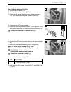
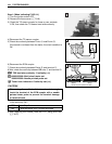
When using the multi-circuit tester, do not storongly
touch the terminal of the ECM coupler with a needle
pointed tester probe to prevent the terminal damage
or terminal bend.
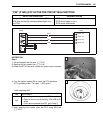
V
3
3
(Black) (Gray)
ECM couplers (Harness side)