


4-66 FI SYSTEM DIAGNOSIS
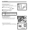
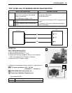
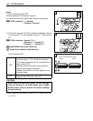
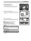
Step 2
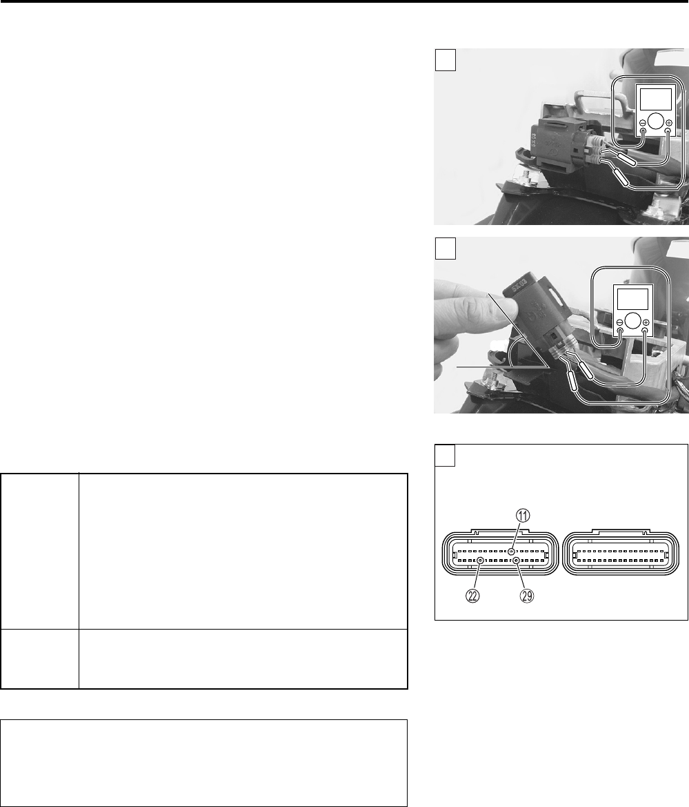
1) Connect the TO sensor coupler and ECM coupler.
2) Insert the needle pointed probes to the lead wire coupler.
3) Turn the ignition switch ON.
4) Measure the voltage between B and B/Br wires.
TO sensor voltage (Normal): 0.4 – 1.4 V
(+ B – - B/Br)
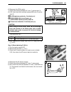
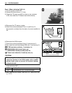
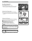
Also, measure the voltage as the motorcycle is leaned.
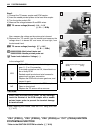
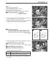
5) Dismount the TO sensor from its bracket and measure the
voltage when it is leaned 65° and more, left and right, from
the horizontal level.
TO sensor voltage (Leaning): 3.7 – 4.4 V
(+ B – - B/Br)
09900-25008: Multi-circuit tester set
09900-25009: Needle pointed probe set
Tester knob indication: Voltage ()
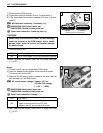
Is the voltage OK?
6) After repairing the trouble, clear the DTC using SDS tool.
(4-27)
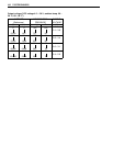
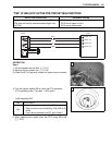
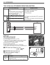
“C24” (P0351), “C25” (P0352), “C26” (P0353) or “C27” (P0354) IGNITION
SYSTEM MALFUNCTION
* Refer to the IGNITION SYSTEM for details. (9-20)
2
V
2
V
65˚
YES
• R, B or B/Br wire open or shorted to ground, or
poor A, L or S connection
• If wire and connection are OK, intermittent trou-
ble or faulty ECM.
• Recheck each terminal and wire harness for
open circuit and poor connection.
• Replace the ECM with a known good one, and
inspect it again.
NO
• Loose or poor contacts on the ECM coupler
• Open or short circuit
• Replace the TO sensor with a new one.
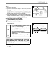
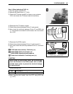
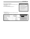
When using the multi-circuit tester, do not storongly
touch the terminal of the ECM coupler with a needle
pointed tester probe to prevent the terminal damage
or terminal bend.
2
(Black) (Gray)
ECM couplers (Harness side)