


FI SYSTEM DIAGNOSIS 4-75
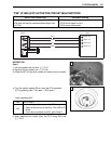
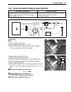
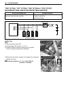
“C31” (P0705) GP SWITCH CIRCUIT MALFUNCTION
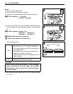
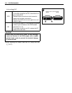
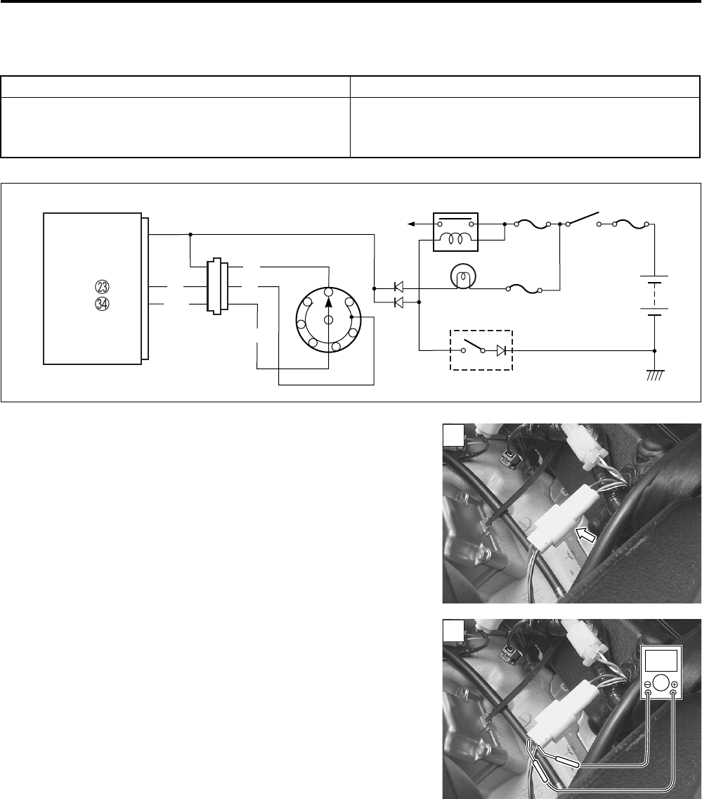
INSPECTION
Step 1
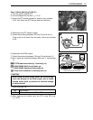
1) Turn the ignition switch OFF.
2) Lift and support the fuel tank. (5-3)
3) Check the GP switch coupler for loose or poor contacts.
If OK, then measure the GP switch voltage.
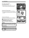
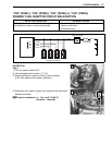
4) Support the motorcycle with a jack.
5) Fold the side-stand to up position.
6) Make sure the engine stop switch is in the “RUN” position.
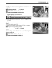
7) Insert the needle pointed probe to the lead wire coupler.
8) Turn the ignition switch ON.
9) Measure the voltage at the wire side coupler between P wire
and B/W wire, when shifting the gearshift lever from 1st to
Top.
GP switch voltage: 0.6 V and more
(+ P – - B/W)
09900-25008: Multi-circuit tester set
09900-25009: Needle pointed probe set
Tester knob indication: Voltage ()
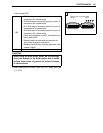
DETECTED CONDITION POSSIBLE CAUSE
No Gear Position switch voltage
Switch voltage is not within the following range.
Switch voltage > 0.6 V
• Gear Position switch circuit open or short
• Gear Position switch malfunction
• ECM malfunction
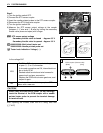
Side-stand switch
Neutral indicator
light
N
1
5
4
2
3
ECM
GP switch
Side-stand relay
Ignition
switch
BI
P
B/W
B/W
GP
To engine stop switch
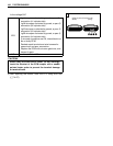
E1
6
P
1
1
V