


4-74 FI SYSTEM DIAGNOSIS
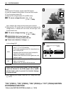
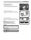
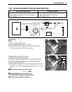
Step 3
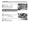
1) Turn the ignition switch OFF.
2) Connect the STP sensor coupler.
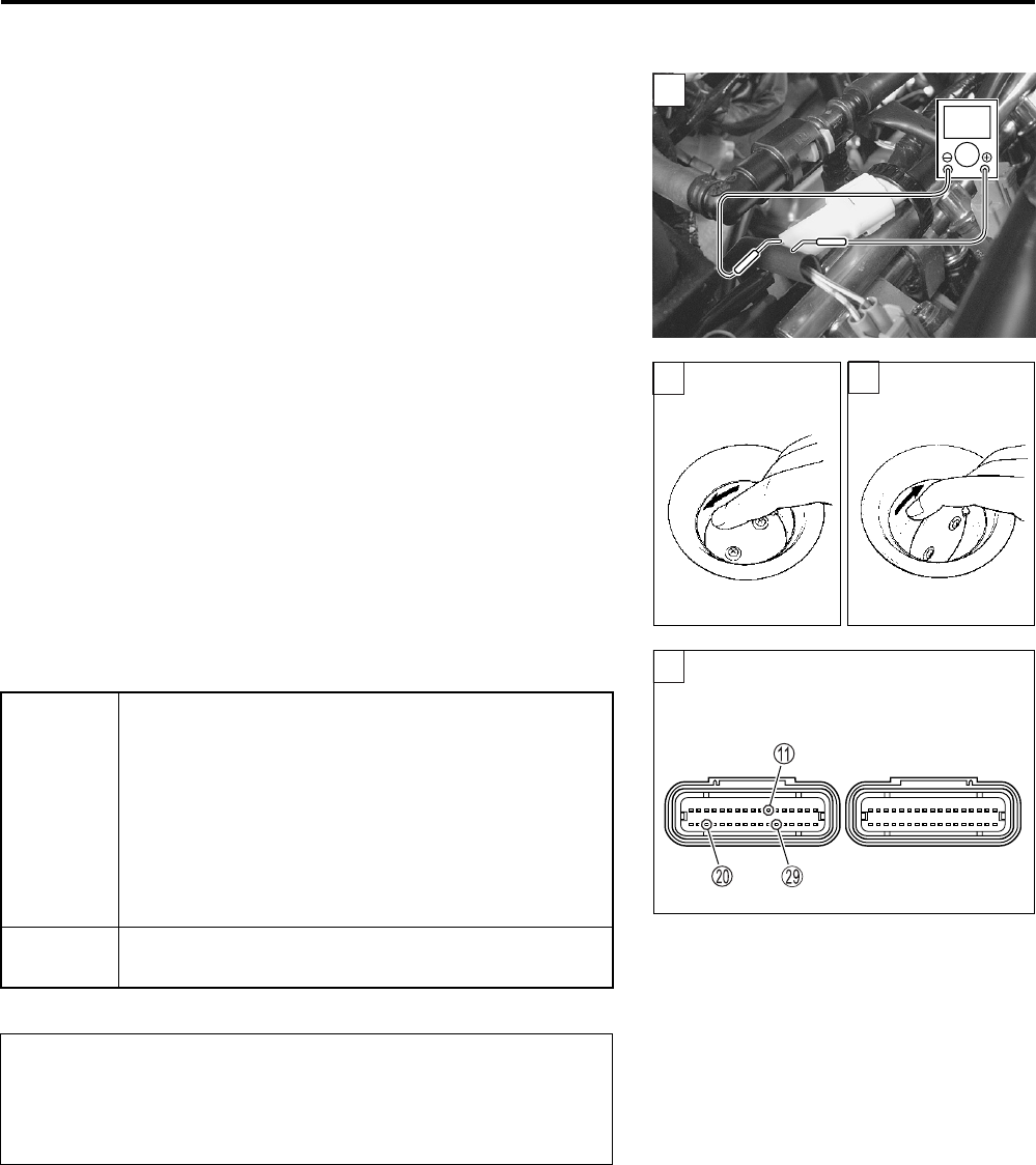
3) Insert the needle pointed probes to the STP sensor coupler.
4) Disconnect the STVA lead wire coupler.
5) Turn the ignition switch ON.
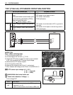
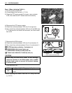
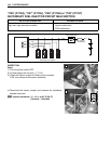
6) Measure the STP sensor output voltage at the coupler
(between + Y wire and - B wire) by turning the secondary
throttle valve (close and open) with a finger.
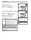
STP sensor output voltage
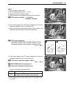
Secondary throttle valve is closed : Approx. 0.5 V
Secondary throttle valve is opened : Approx. 3.9 V
09900-25008: Multi-circuit tester set
09900-25009: Needle pointed probe set
Tester knob indication: Voltage ()
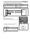
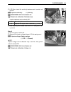
Is the voltage OK?
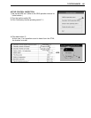
After repairing the trouble, clear the DTC using SDS tool.
(4-27)
3
V
3
3
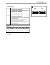
YES
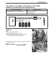
• R, Y/W or B/Br wire open or shorted to ground,
or poor A, J or S connection
• If wire and connection are OK, intermittent trou-
ble or faulty ECM.
• Recheck each terminal and wire harness for
open circuit and poor connection.
• Replace the ECM with a known good one, and
inspect it again.
NO
If check result is not satisfactory, replace STP
sensor with a new one.
When using the multi-circuit tester, do not storongly
touch the terminal of the ECM coupler with a needle
pointed tester probe to prevent the terminal damage
or terminal bend.
3
(Black) (Gray)
ECM couplers (Harness side)