


FI SYSTEM DIAGNOSIS 4-49
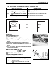
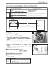
“C15” (P0115-H/L) ECT SENSOR CIRCUIT MALFUNCTION
INSPECTION
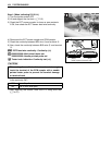
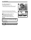
Step 1 (When indicating C15:)
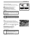
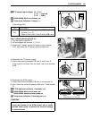
1) Turn the ignition switch OFF.
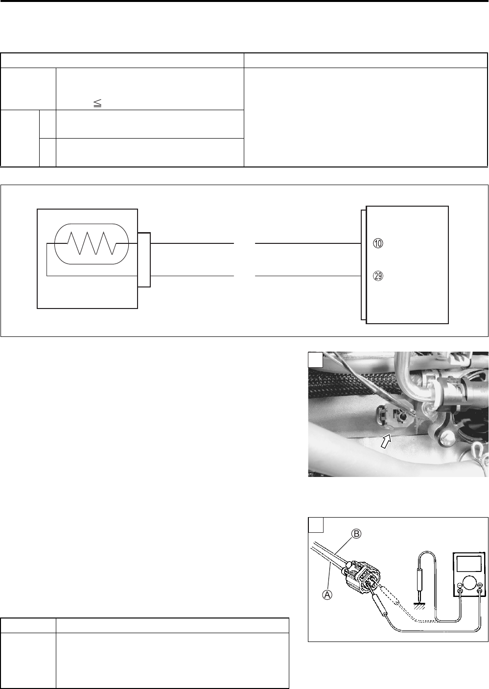
2) Lift and support the fuel tank. (5-3)
3) Check the ECT sensor coupler for loose or poor contacts.
If OK, then measure the ECT sensor voltage at the wire side
coupler.
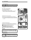
4) Disconnect the coupler and turn the ignition switch ON.
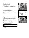
5) Measure the voltage between B/Bl wire terminal A and
ground.
6) If OK, then measure the voltage between B/Bl wire terminal
A and B/Br wire terminal B.
ECT sensor voltage: 4.5 – 5.5 V
(+ B/Bl – - Ground)
(+ B/Bl – - B/Br)
09900-25008: Multi-circuit tester set
Tester knob indication: Voltage ()
Is the voltage OK?
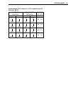
DETECTED CONDITION POSSIBLE CAUSE
C15 Output voltage is not within the following
range.
0.15 V Sensor voltage < 4.85 V
• ECT sensor circuit open or short
• ECT sensor malfunction
• ECM malfunction
P0115
H
Sensor voltage is higher than specified
value.
• ECT sensor circuit open or ground circuit open
• ECT sensor circuit shorted to ground
L
Sensor voltage is lower than specified
value.
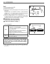
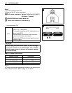
YES Go to Step 2.
NO
• Loose or poor contacts on the ECM coupler
(terminal 0 or S).
• Open or short circuit in the B/Bl wire or B/Br
wire
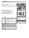
ECM
E2
ECT
B/Br
ECT sensor
B/BI
1
V
1