


5-22 FUEL SYSTEM AND THROTTLE BODY
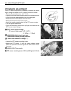
STP SENSOR ADJUSTMENT
If the STP sensor adjustment is necessary, measure the sensor
output voltage and adjust the STP sensor position as follows:
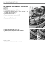
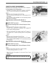
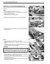
• Remove the air cleaner box . (5-14)
• Loosen the throttle body clamp screws at the intake pipe side.
• Lift up the throttle body assembly from the intake pipe.
• Disconnect the throttle cables from their drum.
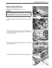
• Disconnect the STVA lead wire coupler.
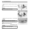
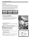
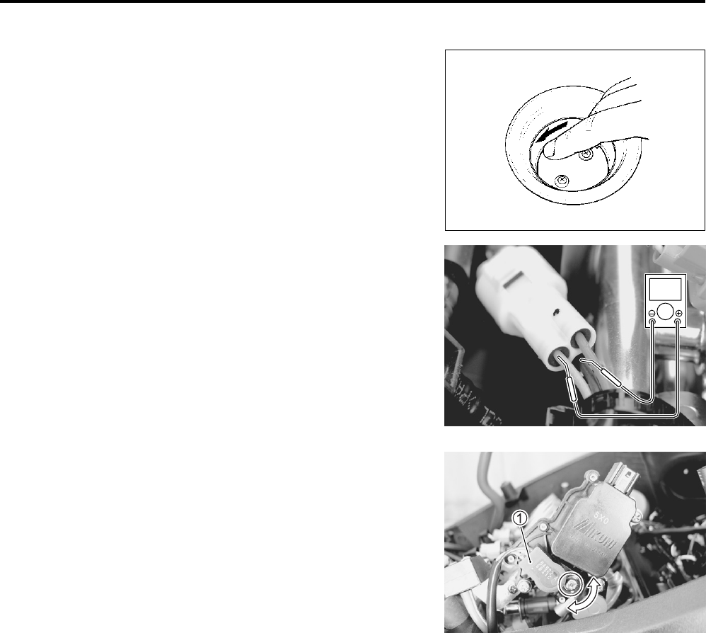
• Insert the needle pointed probes to the STP sensor coupler.
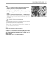
• Turn the ignition switch ON.
• Close the secondary throttle valve by finger, and measure the
STP sensor output voltage.
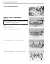
STP sensor output voltage
ST valve is fully closed: 0.57 – 0.67 V
(+ Yellow – - Black)
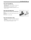
09900-25008: Multi-circuit tester set
09900-25009: Needle pointed probe set
Tester knob indication: Voltage ()
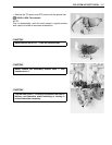
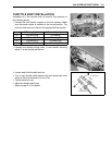
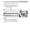
• Loosen the STP sensor mounting screw.
• Adjust the STP sensor 1 until the output voltage comes
within the specified value and tighten the STP sensor mount-
ing screw.
09930-11950: Torx wrench
STP sensor mounting screw: 3.5 N·m (0.35 kgf-m, 2.5 lb-ft)
V