


FI SYSTEM DIAGNOSIS 4-29
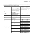
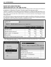
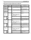
MALFUNCTION CODE AND DEFECTIVE CONDITION
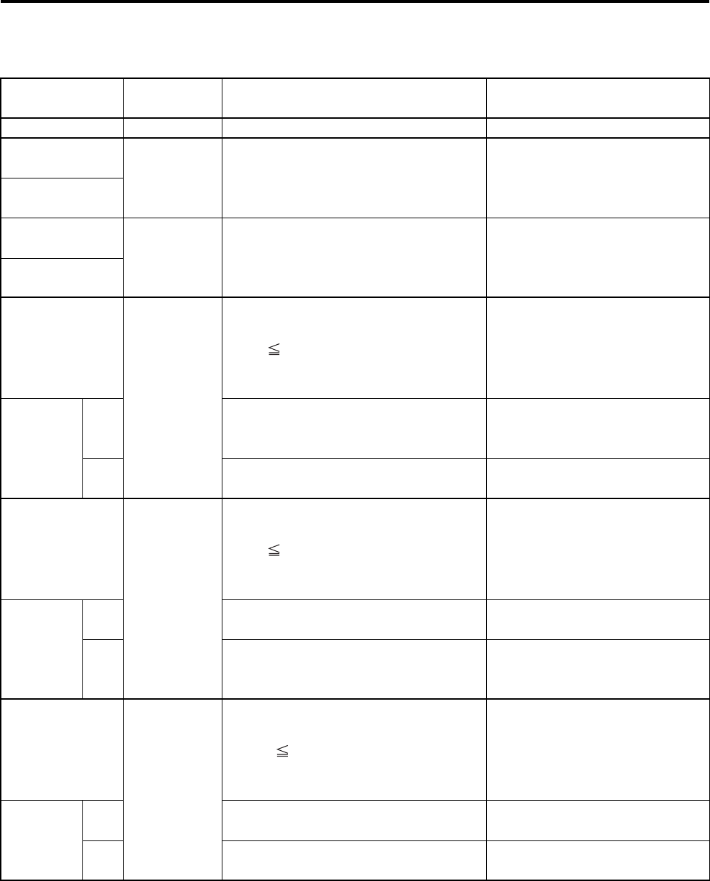
DTC No.
DETECTED
ITEM
DETECTED FAILURE CONDITION CHECK FOR
C00 NO FAULT
––––––––––– –––––––––––
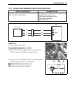
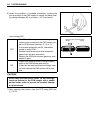
C11
CMP sensor The signal does not reach ECM for 3
sec. or more, after receiving the starter
signal.
CMP sensor wiring and mechan-
ical parts
CMP sensor, intake cam pin,
wiring/coupler connection
P0340
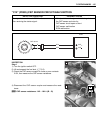
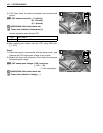
C12
CKP sensor The signal does not reach ECM for 3
sec. or more, after receiving the starter
signal.
CKP sensor wiring and mechan-
ical parts
CKP sensor, lead wire/coupler
connection
P0335
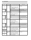
C13
IAP sensor The sensor should produce following
voltage.
0.5 V sensor voltage < 4.85 V
In other than the above range, C13
(P0105) is indicated.
IAP sensor, lead wire/coupler
connection
P0105
H
Sensor voltage is higher than specified
value.
IAP sensor circuit open or
shorted to VCC or ground circuit
open
L
Sensor voltage is lower than specified
value.
IAP sensor circuit shorted to
ground or VCC circuit open
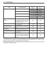
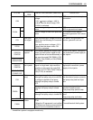
C14
TP sensor The sensor should produce following
voltage.
0.2 V sensor voltage < 4.80 V
In other than the above range, C14
(P0120) is indicated.
TP sensor, lead wire/coupler
connection
P0120
H
Sensor voltage is higher than specified
value.
TP sensor circuit shorted to
VCC or ground circuit open
L
Sensor voltage is lower than specified
value.
TP sensor circuit open or
shorted to ground or VCC circuit
open
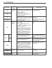
C15
ECT sensor The sensor voltage should be the fol-
lowing.
0.15 V sensor voltage < 4.85 V
In other than the above range, C15
(P0115) is indicated.
ECT sensor, lead wire/coupler
connection
P0115
H
Sensor voltage is higher than specified
value.
ECT sensor circuit open or
ground circuit open
L
Sensor voltage is lower than specified
value.
ECT sensor circuit shorted to
ground