


FUEL SYSTEM (DFI) 3-11
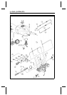
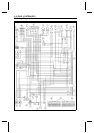
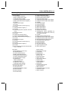
DFI Wiring Diagram
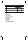
Terminal Names
1. Power Supply to Sensors
2. Main Throttle Sensor Signal
3. Subthrottle Sensor Signal
4. Atmospheric Pressure Sensor Signal
5. Water Temperature Sensor Signal (+)
6. Unused
7. Ignition Switch Signal
8. Unused
9. Camshaft Position Sensor Signal (+)
10. Unused
11. Crankshaft Sensor Signal (+)
12. Unused
13. Power Supply to ECU, Injectors, and Fuel
Pump
14. Ground to sensors
15. Unused
16. Vehicle-down Sensor Signal
17. Inlet Air Pressure Sensor Signal
18. Inlet Air Temperature Sensor Signal (+)
19. Unused
20. Speed Sensor Signal
21. Unused
22. Camshaft Position Sensor Signal (–)
23. Unused
24. Crankshaft Sensor Signal (–)
25. Unused
26. ECU Power Source Circuit Ground to Bat-
tery (–) Terminal
27. Engine Stop Switch S ignal
28. Starter Lockout Switch Signal
29. Electric Starter Button Signal
30. Fuel Pump Relay Signal
31. Subthrottle Valve Actuator Drive Signal
32. Subthrottle Valve Actuator Drive Signal
33. Unused
34. Tachometer Signal
35. Injector #2 Signal
36. Injector #1 Signal
37. Stick Coil #3 Signal
38. Stick Coil #2 Signal
39. Stick Coil #1 Signal
40. Interlock Circuit Signal
41. Self-diagnosis Signal (generated by
grounding this terminal and shown by
FI indicator LED light)
42. Unused
43. Battery Power ON-OFF Signal
44. Subthrottle Valve Actuator Drive Signal
45. Subthrottle Valve Actuator Drive Signal
46. External Diagnosis System Signal
47. FI Indicator LED Light Signal
48. Injector #4 Signal
49. Injector #3 Signal
50. DFI System Ground
51. Ignition System Ground
52. Stick Coil #4 Signal
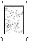
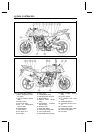
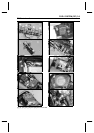
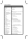
Part Name
A. ECU (Electronic Control U nit)
B. Crankshaft Sensor
C. Inlet Air Pressure Sensor
D. Water Temperature Sensor
E. Atmospheric Pressure Sensor
F. Inlet Air Temperature Sensor
G. Camshaft Position Sensor
H. Speed Sensor
I. Main Throttle Sensor
J. Subthrottle Sensor
K. Injectors #1, #2, #3, #4
L. Subthrottle Valve Actuator
M. Stick Coils #1, #2, #3, #4
N. Engine Stop Switch
O. Joint C onnector D
P. see Electrical System chapter
Q. Ground Terminal
R. Ground Terminal
S. ECU Main Relay
T. Ignition Switch
U. FI Indicator LED Light
V. Tachometer
W. Speedometer
X. Ignition Fuse 10 A
Y. Junction Box
Z. Fuel Pump Relay
a. ECU Fuse 15 A
b. Vehicle-down Sensor
d. Starter Relay
e. Joint Connector C
f. Sealed Battery
g. Fuel Pump
h. Self-diagnosis Terminal
j. Joint Connector B
k. Main Fuse 30 A
m. Throttle Body Assy Connector
n: Connector Locks
p: ECU Connector