


FUEL SYSTEM (DFI) 3-71
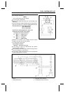
ECU
•
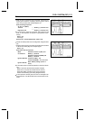
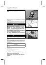
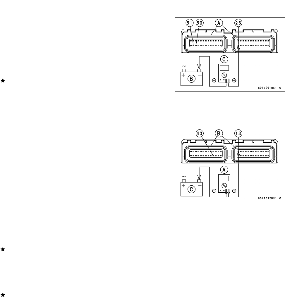
With the ECU connectors [A] connected, check the fol-
lowing ground lead for continuity with the ignition switch
OFF, using a tester and needle adapter set.
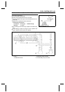
ECU Grounding I nspection
26, 50, or 51 (BK/Y)
Terminal
←→
Battery (–) Terminal: 0 Ω
Engine Ground
←→
Battery (–) Terminal: 0 Ω
If no continuity, check the connector, the engine ground
lead, or main harness, and repair or replace them if nec-
essary.
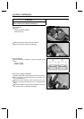
Battery [B]
Test er [C ]
Special Tool - Needle Adapter Set: 57001–1457
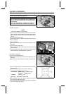
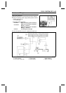
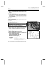
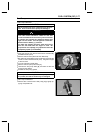
•
Check the ECU power source voltage with a digital meter
[A].
○
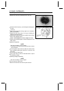
Position the terminal in accordance with terminal numbers
of ECU connectors [B] in this chapter figure.
Battery [C]
ECU Power Source Inspection
Meter
Connections:
between Terminal 13 (W/Y) and
Battery (–) Terminal
between Terminal 43 (W/BK) and
Battery (–) Terminal
Ignition SW OFF: Terminal 13 (W/Y) : 0 V,
Terminal 43 (W/BK) : 12.6 V or more
Ignition SW ON:
Both: Battery Voltage (12.6 V or
more)
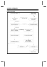
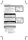
If the meter does not read as specified, check the follow-
ing:
Main Fuse 30 A (see Electrical System chapter)
ECU Fuse 15 A (see DFI Power S ource section)
ECU Main Relay (see DFI Power Source section)
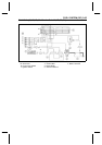
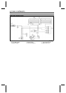
Power Source Wiring (see wiring diagram below)
If the inspection checks good, the ECU is damaged. Re-
place the ECU. The ECU itself cannot be checked or ser-
viced.