CRANKSHAFT/TRANSMISSION 9-21
Crankshaft and Connecting Rods
•
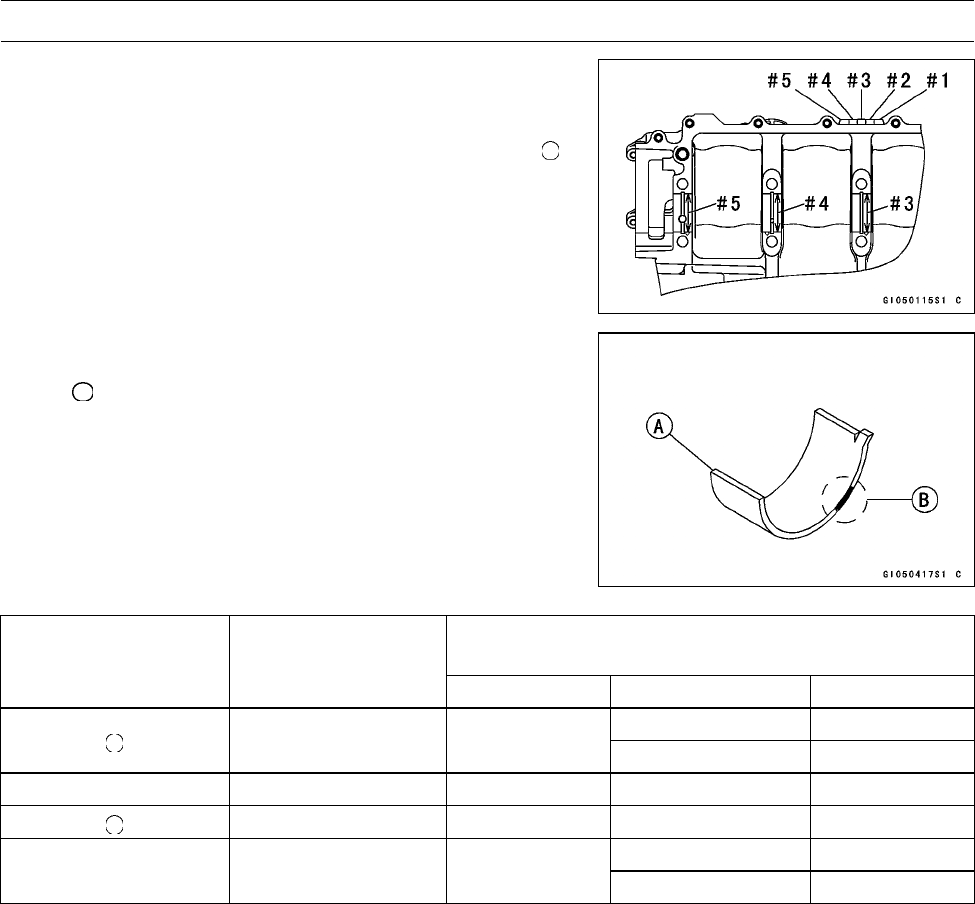
Measure the main bearing i nside diameter, and mark the
upper crankcase half in accordance with the inside diam-
eter.
Crankcase Main Bearing Inside Diameter Marks : "
"
or no mark.
•
Tighten the crankcase bolts to the specified torque (see
Crankcase Assembly).
NOTE
○
The mark already on the upper crankcase half should
almost coincide with the measurement.
Crankcase Main Bearing Inside Diameter Marks
36.000 ∼ 36.008 mm (1.4173 ∼ 1.4176 in.)
None 36.009 ∼ 36.016 mm (1.4177 ∼ 1.4179 in.)
•
Select the proper bearing insert [A] in accordance with the
combination of the crankcase and crankshaft coding.
Size Color [B]
Bearing Insert*
Crankcase Main
Bearing Inside
Diameter M arking
Crankshaft Main
Journal Diameter
Marking
Size Color Part Number Journal Nos.
92028–1868 3, 5
1 Brown
92028–1829 1, 2, 4
None 1 Black 92028–1867 3, 5
None 92028–1828 1, 2, 4
92028–1866 3, 5
None None Blue
92028–1827 1, 2, 4
* The bearing inserts for Nos. 1, 2 and 4 journals have an oil groove, respectively.
•
Install the new inserts in the crankcase halves and check
insert/journal clearance with the plastigage.


