3-64 FUEL SYSTEM (DFI)
Stick Coils (#1, #2, #3, #4: Service Code 51, 52, 53, 54)
Stick Coil #1: Ignition Coil (Service Code 51)
Stick Coil #2: Ignition Coil (Service Code 52)
Stick Coil #3: Ignition Coil (Service Code 53)
Stick Coil #4: Ignition Coil (Service Code 54)
Removal/Installation
CAUTION
Never drop the stick coils, especially on a hard sur-
face. Such a shock to the stick coil can damage it.
•
See the Ignition System section in the Electrical System
chapter.
Input Voltage Inspection
NOTE
○
Be sure the battery is fully charged.
•
Turn the ignition switch OFF.
•
Remove the ECU (see this chapter). Do not disconnect
the ECU connector.
•
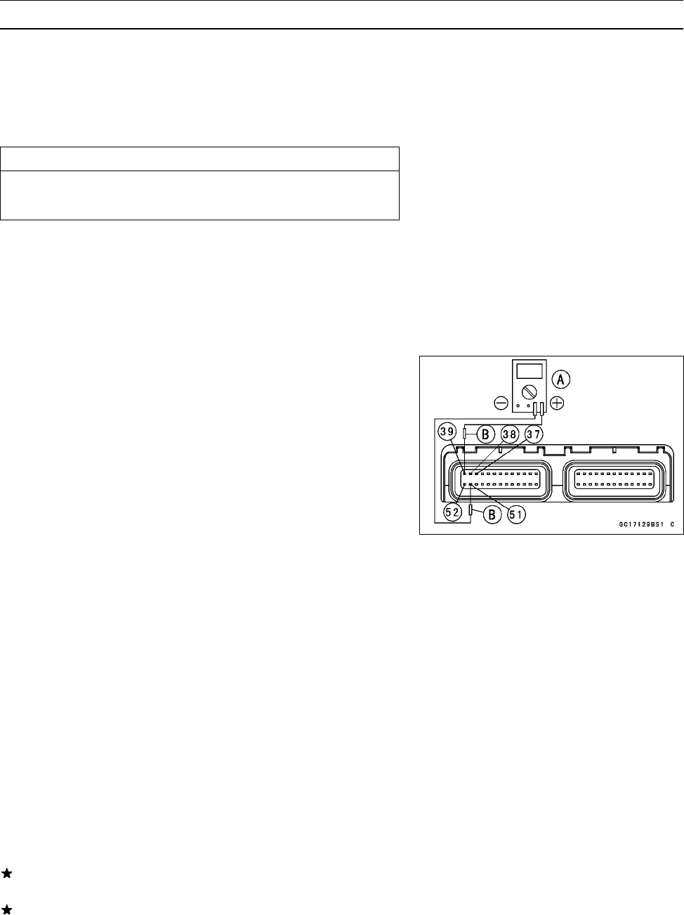
Connect a digital voltmeter [A] as shown, with the needle
adapter set [B].
○
Measure the input voltage to each primary winding of the
ignition coils with the engine stopped, and with the con-
nectors joined.
•
Turn the ignition switch ON.
Stick Coil Input Voltage at ECU
Connections for Stick Coil #1
Meter (+) → BK lead (terminal 39)
Meter (–) → BK/Y lead (terminal 51)
Connections for Stick Coil #2
Meter (+) → BK/G lead (terminal 38)
Meter (–) → BK/Y lead (terminal 51)
Connections for Stick Coil #3
Meter (+) → BK/W lead (terminal 37)
Meter (–) → BK/Y lead (terminal 51)
Connections for Stick Coil #4
Meter (+) → BK/O lead (terminal 52)
Meter (–) → BK/Y lead (terminal 51)
Input Voltage at ECU
Standard: Battery Voltage (12.6 V or more)
If the reading is out of the standard, check the wiring (see
next wiring diagram).
If the reading is good, the input voltage is normal. Crank
the engine, and check the peak voltage of the stick coils
(see Electrical System chapter) in order to check the pri-
mary coils.


