3-84 FUEL SYSTEM (DFI)
Fuel Injectors
Injector Resistance Inspection
•
Remove the f uel tank (see Fuel Tank Removal).
•
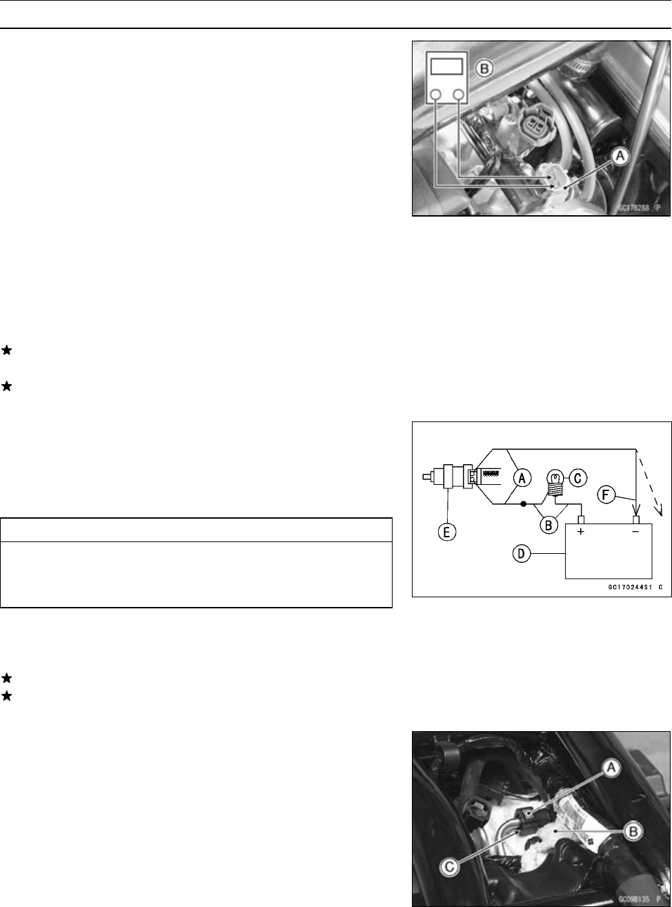
Disconnect the connector f rom the injector [A] (see Throt-
tle Body Assy Disassembly/Assembly).
•
Measure the injector resistance with the hand tester [B].
Special Tool - H and Tester: 57001–1394
Injector Resistance
Connections to Injector
Meter (+) Meter (–)
#1: W/R ←→ BL/R Terminal
#2: W/R ←→ BL/G Terminal
#3: W/R ←→ BL/BK Terminal
#4: W/R ←→ BL/Y Terminal
Standard: about 11.7 ∼ 12.3 Ω @20°C (68°F)
If the reading is out of the range, perform the “Injector Unit
Tes t”.
If the reading is normal, perform the “Injector Unit Test”
for confirmation.
Injector Unit Test
•
Use two leads [A] and the same test light set [B] as in
“Injector Signal Test”.
Rating of Bulb [C]: 12 V × (3 ∼ 3.4) W
12 V Battery [D]
CAUTION
Be sure to connect the bulb in series. The bulb
works as a current limiter to protect the solenoid
in the injector from excessive current.
•
Connect the test light set to the injector [E] as shown.
•
Open and connect [F] the end of the lead to the battery
(–) terminal repeatedly. The injector should click.
If the injector does not click, replace the injector.
If the injector clicks, check the wiring again. If the wiring
is good, replace the injector (may be clogged) or ECU.
Injector Fuel Line Inspection
•
While pinching the fuel pump outlet hose joint locks [A]
with fingers, pull the joint out along the delivery pipe (see
Fuel Tank Removal).
Cloth [B]
Pump Outlet Hose Joint [C]


