


3-82 FUEL SYSTEM (DFI)
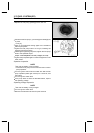
Fuel Injectors
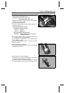
Output Voltage Inspection
•
Turn the ignition switch OFF.
•
Remove the ECU (see ECU section).
•
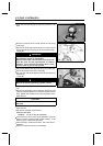
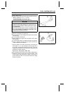
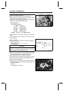
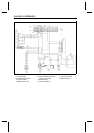
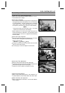
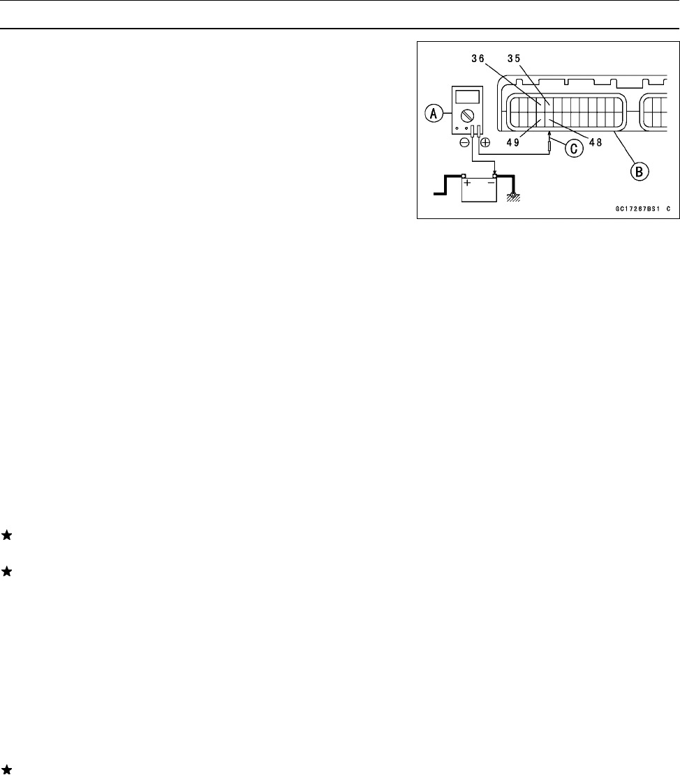
Connect a digital voltmeter [A] to t he ECU connector [B]
with the needle adapter set [C].
Special Tool - N eedle Adapter Set: 57001-1457
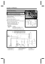
Injector Output Voltage
Connections to Injector #1
Meter (+) → BL/R lead (terminal 36)
Meter (–) → Battery (–) Terminal
Connections to Injector #2
Meter (+) → BL/G lead (terminal 35)
Meter (–) → Battery (–) Terminal
Connections to Injector #3
Meter (+) → BL/BK lead (terminal 49)
Meter (–) → Battery (–) Terminal
Connections to Injector #4
Meter (+) → BL/Y lead (terminal 48)
Meter (–) → Battery (–) Terminal
•
Turn the ignition switch ON.
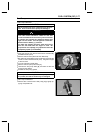
Output Voltage at Injector Connector
Standard: Battery Voltage (12.6 V or more)
If the output voltage is normal, perform “Injector Signal
Tes t”.
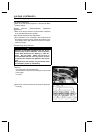
If the output voltage is out of the standard, turn the ignition
switch OFF, remove the fuel tank, and check the injector
wiring for continuity.
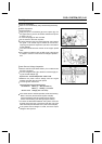
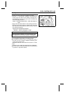
Injector Wiring Inspection
ECU Connector Injector Connectors
Terminal 36 →
Injector #1 Terminal (BL/R)
Terminal 35
→
Injector #2 Terminal (BL/G)
Terminal 49 →
Injector #3 Terminal (BL/BK)
Terminal 48
→
Injector #4 Terminal (BL/Y)
If the wiring is good, inspect the resistance of the injectors
(see Injector Resistance Inspection in chapter).
•
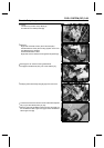
Remove the needle adapter.
•
Apply silicone sealant to the seals of the ECU connector
for w aterproofing.