


5-16 ENGINE TOP END
Camshaft, Camshaft Chain
•
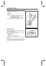
Position the crankshaft at #1, 4 piston TDC.
•
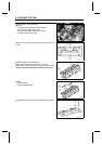
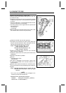
Pull the tension side (exhaust side) [A] of the chain taut
to install the chain.
•
Engage the camshaft chain with the camshaft sprockets
so that the timing marks on the sprockets are positioned
as shown.
○
The timing marks of #1, 4T must be aligned with the lower
surface of crankcase of rear side [B].
○
The timing marks must be aligned with the cylinder head
upper surface [C].
EX mark [D]
IN mark [E]
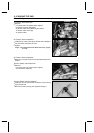
•
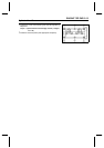
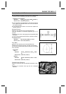
Before installing the camshaft cap and chain guide, install
the camshaft chain tensioner body temporally.
•
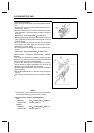
Install the camshaft cap and chain guide [A].
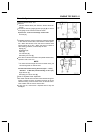
○
First tighten the camshaft cap and all chain guide bolts
evenly to seat the camshaft in place, then tighten all bolts
following the specified tightening sequence.
Torque - Camshaft Cap Bolts (1∼16, 19, 20):
12 N·m (1.2 kgf·m, 104 in·lb)
Camshaft Chain Guide Bolts (17, 18):
12 N·m (1.2 kgf·m, 104 in·lb)
•
Tighten the camshaft chain tensioner (see Camshaft
Chain Tensioner Installation).
•
Install the cylinder head cover (see Cylinder Head Cover
Installation).
Camshaft, Camshaft Cap Wear
•
Remove:
Camshaft Chain Guide
Camshaft Cap
•
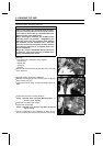
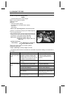
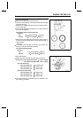
Cut strips of plastigage to journal width. Place a strip
on each journal parallel to the camshaft installed in the
correct position.
•
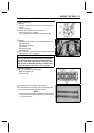
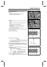
Measure each clearance between the camshaft journal
and the camshaft cap using plastigage (press gauge) [A].
•
Tighten:
Torque - Camshaft Cap Bolts: 12 N·m (1.2 kgf·m, 104 in·lb)
Camshaft Chain Guide Bolts: 12 N·m (1.2 kgf·m,
104 in·lb)
NOTE
○
Do not turn the camshaft when the plastigage is be-
tween the journal and camshaft cap.
Camshaft Journal, Camshaft Cap Clearance
Standard: 0.028 ∼ 0.071 mm (0.0011 ∼ 0.0028 in.)
Service Limit: 0.16 mm (0.0063 in.)