


ELECTRICAL SYSTEM 16-41
Ignition System
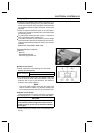
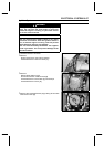
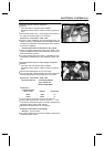
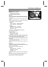
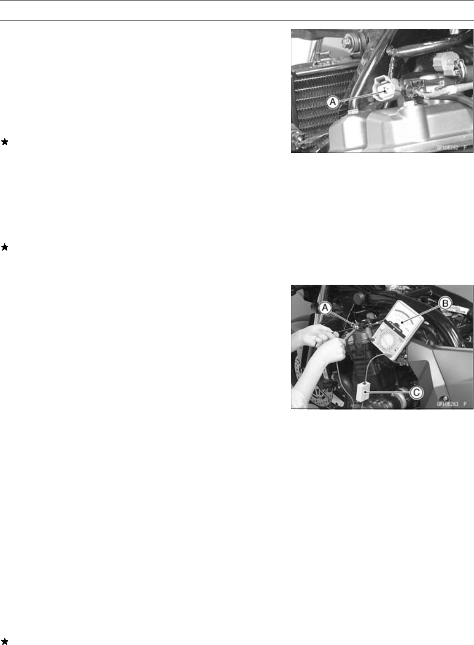
Camshaft Position Sensor Inspection
•
Remove:
Fuel Tank (see Fuel System (DFI) chapter)
Camshaft Position Sensor Lead Connector [A] (discon-
nect)
•
Set the hand tester to the × 10 Ω range and connect it to
the yellow and black leads in the connector.
Special Tool - Hand Tester: 57001–1394
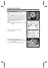
If there is more resistance than the specified value, the
sensor coil has an open lead and must be replaced. Much
less than this resistance means the sensor coil is shorted,
and m ust be replaced.
Camshaft Position Sensor Resistance: 400 ∼ 460 Ω
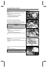
•
Using the highest resistance range of the tester, mea-
sure the resistance between the camshaft position sensor
leads and chassis ground.
Any tester reading less than infinity (∞) indicates a short,
necessitating replacement of the camshaft position sen-
sor.
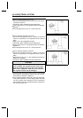
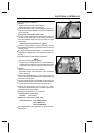
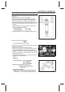
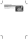
Camshaft Position Sensor Peak Voltage Inspection
•
Remove:
Fuel Tank (see Fuel System (DFI) chapter)
Camshaft Position Sensor Lead Connector [A] (discon-
nect)
•
Set the hand tester [B] to the 10 V DC range.
•
Connect the peak voltage adapter [C] to the hand tester
and camshaft position sensor leads in the connector.
Special Tool - Hand Tester: 57001–1394
Recommended Tool- Peak Voltage Adapter
Type: KEK-54-9-B
Brand: KOWA SEIKI
Connections:
Camshaft Position
Sensor Lead
Adapter Hand Tester
Black
←
Red
→
(+)
Yellow
←
Black
→
(–)
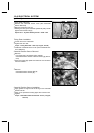
•
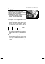
Turn the ignition switch and engine stop switch on.
•
Pushing the starter button, turn the engine 4 ∼ 5sec-
onds w ith the transmission gear in neutral to measure the
camshaft position sensor peak voltage.
•
Repeat the measurement 5 or more times.
Camshaft Position Sensor Peak Voltage
Standard:
0.2 V or more
If the peak voltage is lower than the standard, inspect the
camshaft position sensor.