16-78 ELECTRICAL SYSTEM
Switches and Sensors
Fuel Level Sensor Inspection
•
Remove:
Fuel Tank (see Fuel System (DFI) chapter)
•
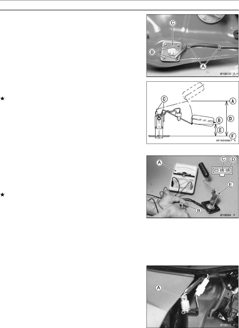
Open the clamps [A].
•
Remove:
Bolts [B]
Fuel Level Sensor [C]
•
Check that the float moves up and down smoothly without
binding. It should go down under its own weight.
If the float does not move smoothly, replace the sensor.
Float in Full Position [A]
Float in Empty Position [B]
Float Arm Stoppers [ C]
105.2 ∼ 112.2 mm (4.142 ∼ 4.417 in.) from the Sensor
Base Line [D]
33.6 ∼ 40.6 mm (1.32 ∼ 1.60 in.) from the Sensor Base
Line [E]
Sensor Base Line [F]
•
Using the hand tester [A], measure the resistance across
the terminals in the fuel level sensor lead connector [B].
Black/Yellow [C]
White/Yellow [D]
Special Tool - H and Tester: 57001–1394
If the tester readings are not as specified, or do not
change smoothly according as the float moves up and
down, replace t he sensor.
Fuel Level Sensor Resistance
Standard: Full position: 4 ∼ 10 Ω
Empty position [E]: 90 ∼ 100 Ω
•
Apply a non-permanent locking agent to the threads of
the level sensor mounting bolts and tighten it.
Torque - Fuel Level Sensor Bolts: 6.9 N·m (0.70 kgf·m, 61
in·lb)
Fuel Reserve Switch Inspection
•
Fill the fuel tank with fuel.
•
Close the fuel tank cap surely.
•
Remove:
Right Frame Cover (see Frame chapter)
•
Disconnect the fuel level sensor connector [A].


