11 -10 FINAL DRIVE
Sprocket, Coupling
Engine Sprocket Removal
•
Remove:
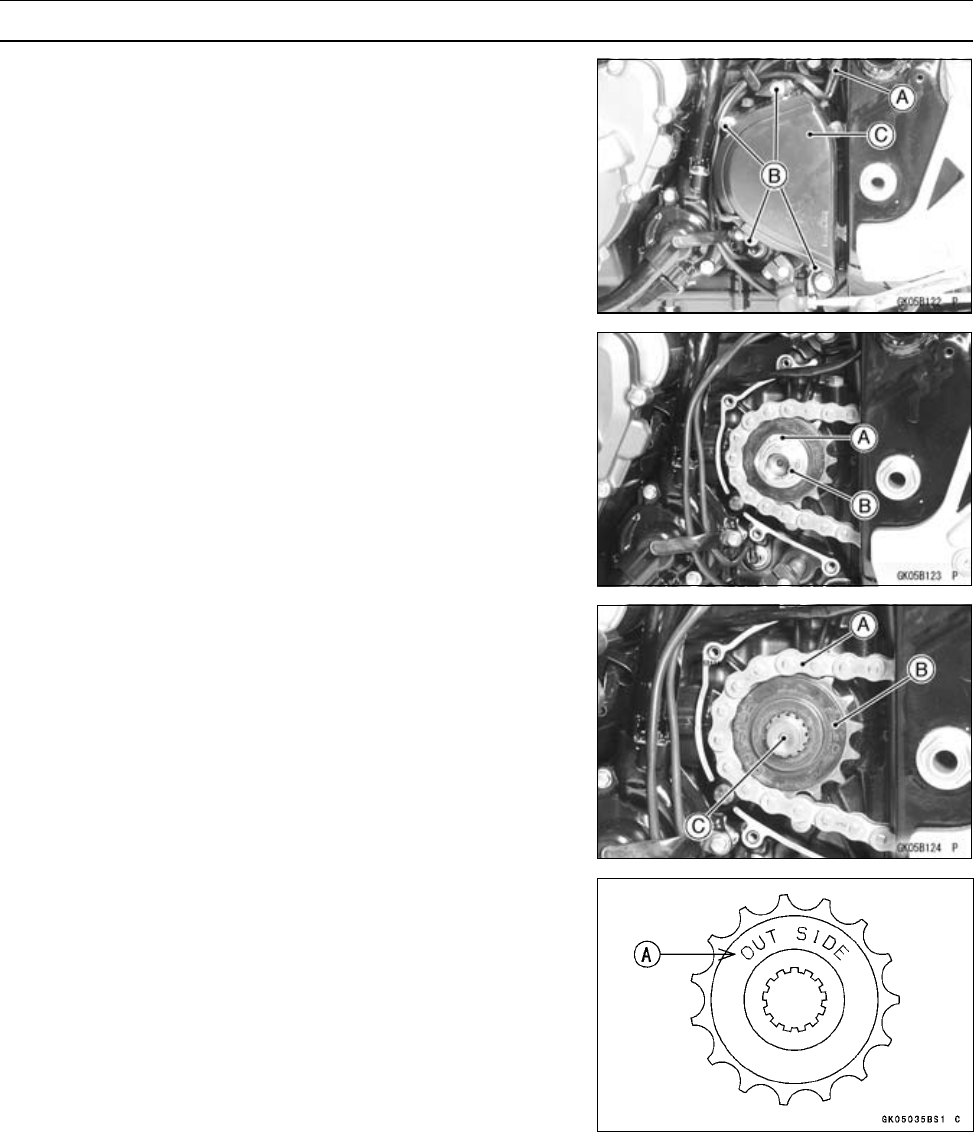
Speed Sensor Connector [A]
Engine Sprocket Cover Bolts [B]
Engine Sprocket Cover [C] with Speed Sensor
•
Flatten out the bended washer [A].
•
Remove the engine sprocket nut [B] and washer.
NOTE
○
When loosening the engine sprocket nut, hold the rear
brake on.
•
Using the jack, raise the rear wheel off the ground.
Special Tool - Jack : 57001–1238
•
Loosen the drive chain (see Slack Adjustment).
•
Remove the drive chain from the rear sprocket toward the
right.
•
Disengage the drive chain [A] from the engine sprocket
[B].
•
Pull the engine sprocket off the output shaft [C].
Engine Sprocket Installation
•
Replace the sprocket washer and axle cotter pin.
•
Install the engine sprocket so that “OUTSIDE” letters [A]
face outward.
•
Apply molybdenum disulfide oil to the threads of the out-
put shaft and the seating surface of the engine sprocket
nut.
•
After torquing the engine sprocket nut, bend the one side
of the washer over the nut.
NOTE
○
Tighten the nut while applying the rear brake.
•
Tighten:
Torque - Engine Sprocket Nut: 1 25 N·m (13 kgf·m, 92 ft·lb)
Engine Sprocket Cover Bolts: 9.8 N·m (1.0 kgf·m,
87 in·lb)
•
Adjust the drive chain slack after installing the sprocket
(see Drive Chain Slack Adjustment in the Periodic Main-
tenance chapter).


