


3-52 FUEL SYSTEM (DFI)
Atmosp heric Pressure Sensor (Service Code 15)
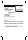
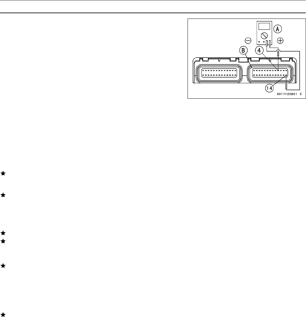
Output Voltage Inspection
•
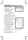
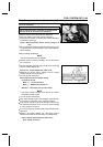
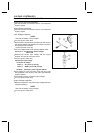
Measure the output voltage at the ECU in the same way
as input voltage inspection. Note the following.
Digital Meter [A]
ECU Connector [B]
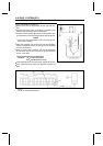
Atmospheric Pressure Sensor Output Voltage
Connections to ECU
Meter (+) → G/W lead (terminal 4)
Meter (–) → BR/BK lead (terminal 14)
Usable Range:
3.74 ~ 4.26 V DC at the standard
atmospheric pressure (101.32 kPa,
76 cmHg abs.)
NOTE
○
The output voltage changes according t o the local at-
mospheric pressure.
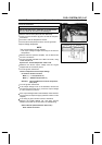
•
Turn the ignition switch OFF.
If the output voltage is within the usable range, check the
ECU for its ground, and power supply (see this chapter).
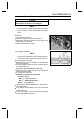
If the output voltage is out of the standard, remove the
seat cover and check the wiring. And if the output voltage
is 4.8 V, the ECU is normal.
If the wiring is good, check t he sensor for various vacuum.
If the output voltage for various vacuum is normal, check the ECU for its ground, and power supply
(see ECU section).
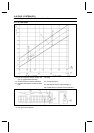
○
Determine the local altitude (elevation).
If you know the local atmospheric pressure using a barometer, substitute the atmospheric pressure
for Pv (throttle vacuum) in the vacuum sensor chart (see inlet air pressure sensor section in this
chapter).
○
Get the usable range of the atmospheric pressure sensor output voltage in the same way as O utput
Voltage Inspection of the inlet air pressure sensor and check if Va (output voltage) is within the
usable r ange or not.
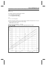
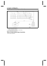
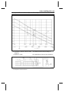
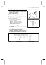
If you know the local altitude, use the following chart.
For example:
Suppose the local altitude is 1300 m (4200 ft) and the sensor output voltage Va is 3.3 V.
Plot this H (1300 m ) at a point [1] on the following chart and draw a vertical l ine through the point.
Then, you can get the usable range [2] of the sensor output voltage.
Usable Range = 3.2 ∼ 3.64 V
Plot Va (3.3 V) on the vertical line → Point [3]
Results: In the chart, Va is within the usable range and the sensor is normal.