CRANKSHAFT/TRANSMISSION 9-13
Crankshaft and Connecting Rods
Crankshaft Removal
•
Split the crankcase (see Crankcase S plitting).
•
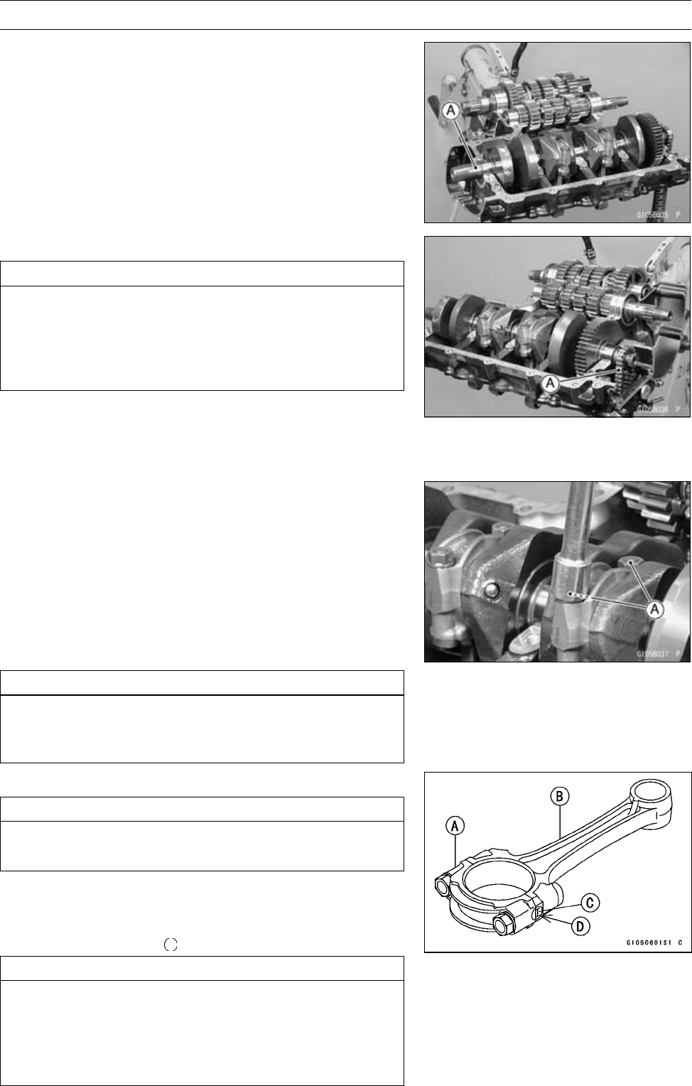
Remove the crankshaft [A].
Crankshaft Installation
CAUTION
If the crankshaft, bearing inserts, or crankcase
halves are replaced with new ones, select the bear-
ing inserts and check clearance with a plastigage
(press gauge) before assembling engine to be sure
the correct bearing inserts are installed.
•
Apply molybdenum disulfide oil solution to the crankshaft
main bearing inserts.
•
Install the crankshaft with the camshaft chain [A] hanging
on it.
Connecting Rod Removal
•
Split the crankcase (see Crankcase S plitting).
•
Remove the connecting rod nuts [A].
•
Remove the crankshaft.
NOTE
○
Mark and record the locations of the connecting rods
and their big end caps so that they can be reassembled
in their original positions.
•
Remove the connecting rods from the crankshaft.
CAUTION
Discard the connecting rod bolts. To prevent dam-
age to the crankpin surfaces, do not allow the con-
necting rod bolts to bump against the crankpins.
Connecting Rod Install ation
CAUTION
To minimize vibration, the connecting rods should
have the sam e weight mark.
BigEndCap[A]
Connecting Rod [B]
Weight Mark, Alphabet [C]
Diameter Mark [D]: “
”ornomark
CAUTION
If the connecting rods, big end bearing inserts, or
crankshaft are replaced with new ones, select the
bearing insert and check clearance with a plasti-
gage (press gauge) before assembling engine to be
sure the correct bearing inserts are installed.


