


CRANKSHAFT/TRANSMISSION 9-19
Crankshaft and Connecting Rods
•
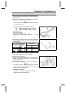
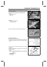
Measure the connecting rod big end inside diameter, and
mark each connecting rod big end in accordance with the
inside diameter.
•
Tighten the connecting rod big end nuts to the specified
torque (see Connecting Rod Installation).
NOTE
○
The mark already on the big end should almost coincide
with the measurement.
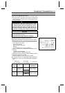
Connecting Rod Big End Inside Diameter Marks
None
38.000 ∼ 38.008 mm (1.4961 ∼ 1.4964 in.)
38.009 ∼ 38.016 mm (1.4964 ∼ 1.4967 in.)
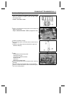
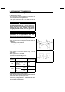
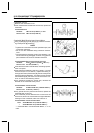
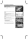
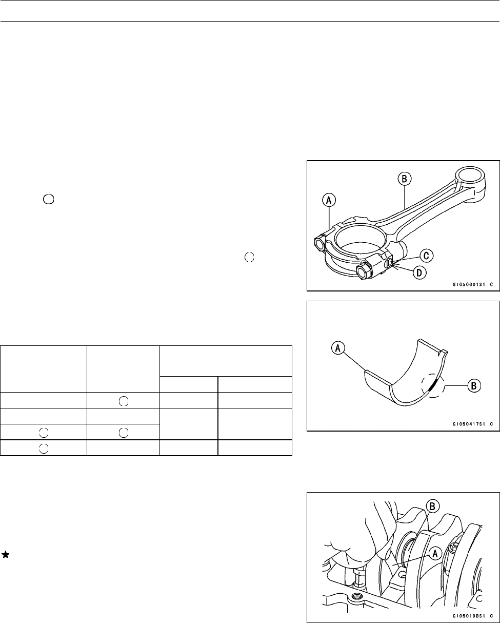
BigEndCap[A]
Connecting Rod [B]
Weight Mark, Alphabet [C]
Diameter Mark (Around Weight Mark) [D]: “
”orno
mark
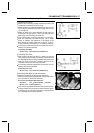
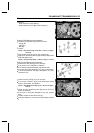
•
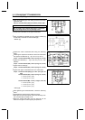
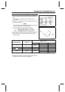
Select the proper bearing insert [A] in accordance with the
combination of the connecting rod and crankshaft coding.
Size Color [B]
Bearing Insert
Con-rod Big End
Inside Diameter
Marking
Crankpin
Diameter
Marking
Size Color Part Number
None Brown 92139–1110
None None
Black 92139–1109
None Blue 92139–1108
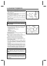
•
Install the new inserts in the connecting rod and check
insert/crankpin clearance with the plastigage.
Crankshaft Side Clearance
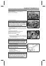
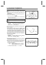
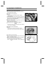
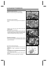
•
Insert a thickness gauge [A] between the crankcase main
bearing and the crank web at the No. 2 journal [B] to
determine clearance.
If the clearance exceeds the service limit, replace t he
crankcase halves as a set.
NOTE
○
The upper and lower crankcase halves are machined
at the factory in the assembled state, so the crankcase
halves must be replaced as a set.
Crankshaft Side Clearance
Standard: 0.05 ∼ 0.20 mm (0.0020 ∼ 0.0079 in.)
Service Limit: 0.40 mm (0.0157 in.)