


FUEL SYSTEM (DFI) 3-1
3
Fuel System (DFI)
Table of Contents
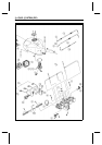
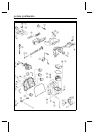
Exploded View........................................................................................................................ 3-4
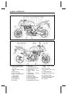
DFI Parts Location.................................................................................................................. 3-8
DFI Wiring Diagram ................................................................................................................3-10
Specifications ......................................................................................................................... 3-12
Special Tools .......................................................................................................................... 3-14
DFI Servicing Precautions ...................................................................................................... 3-15
DFI Servicing Precautions ................................................................................................ 3-15
Troubleshooting t he DFI System ............................................................................................ 3-17
Outline ................................................................................................................................. 3-17
Outline............................................................................................................................... 3-17
Inquiries to Rider.................................................................................................................. 3-21
Inquiries to Rider............................................................................................................... 3-21
DFI System Troubleshooting G uide ....................................................................................... 3-24
DFI System Troubleshooting Guide.................................................................................. 3-24
Self-Diagnosis ........................................................................................................................ 3-33
Self-diagnosis Outline.......................................................................................................... 3-33
Self-diagnosis Outline ....................................................................................................... 3-33
Self-diagnosis Procedures................................................................................................... 3-33
Self-diagnosis Procedures................................................................................................ 3-33
Service Code Clearing Procedures ..................................................................................... 3-34
Service Code Clearing Procedures................................................................................... 3-34
How to Read Service Codes................................................................................................ 3-36
How to Read Service Codes............................................................................................. 3-36
How to Erase S ervice Codes............................................................................................... 3-36
How to Erase Service Codes............................................................................................ 3-36
Service Code Table.............................................................................................................. 3-37
Service Code Table........................................................................................................... 3-37
Backups ............................................................................................................................... 3-38
Backups ............................................................................................................................ 3-38
Main Throttle Sensor (Service Code 11) ................................................................................ 3-40
Main Throttle Sensor Removal/Adjustment ...................................................................... 3-40
Input Voltage Inspection.................................................................................................... 3-40
Output Voltage Inspection................................................................................................. 3-41
Resistance Inspection....................................................................................................... 3-42
Inlet Air Pressure Sensor (Service Code 12).......................................................................... 3-43
Removal............................................................................................................................ 3-43
Installation......................................................................................................................... 3-43
Input Voltage Inspection.................................................................................................... 3-43
Output Voltage Inspection................................................................................................. 3-44
Inlet Air Temperature Sensor (Service Code 13).................................................................... 3-47
Removal/Installation.......................................................................................................... 3-47
Output Voltage Inspection................................................................................................. 3-47
Sensor Resistance Inspection .......................................................................................... 3-48
Water Temperature Sensor (Service Code 14) ...................................................................... 3-49
Removal/Installation.......................................................................................................... 3-49
Output Voltage Inspection................................................................................................. 3-49