PERIODIC MAINTENANCE 2-17
Periodic M aintenance Procedures
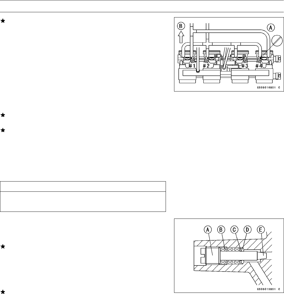
If any one vacuum measurement is out of the standard
measurement after synchronization, adjust the bypass
screws [A].
Front [B]
Special Tool - Pilot Screw Adjuster, C: 57001–1292
•
Adjust the lowest vacuum between #1 and #2 to the high-
est of #1 and #2.
•
Adjust the lowest vacuum between #3 and #4 to the high-
est of #3 and #4.
•
Open and close the throttle valves after each measure-
ment and adjust the idle speed as necessary.
•
Inspect the vacuums as before.
If all vacuums are within the specification, finish the en-
gine vacuum synchronization.
If any vacuum can not be adjusted within the specification,
remove the bypass screws #1 ∼ #4 and clean them.
○
Turn in the bypass screw and count the number of turns
until it seats fully but not tightly. Record the number of
turns.
Torque - Bypass Screw: 0.2 N·m (0.02 kgf·m, 1.7 in·lb)
CAUTION
Do not over tighten them. They could be damaged,
requiring replacement.
•
Remove the bypass screw [A], spring [B], washer [C] and
O-ring [D].
○
Check the bypass screw and its hole for carbon deposits.
If any carbon accumulates, wipe the carbon off the bypass
screw and the hole, using a cotton pad penetrated with a
high-flash point solvent.
○
Replace the O-ring with a new one.
○
Check the tapered portion [E] of the bypass screw for
wear or damage.
If the bypass screw is worn or damaged, replace it.
•
Turn in the bypass screw until it seats fully but not tightly.
Torque - Bypass Screw: 0.2 N·m (0.02 kgf·m, 1.7 in·lb)


