


ENGINE BOTTOM END/TRANSMISSION 7-9
Crankcase
•
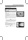
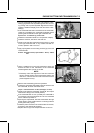
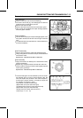
Turn the crankshaft [A] to BDC [B], and install the crank-
shaft jig [C] between the flywheels opposite the connect-
ing rod big end to protect flywheel alignment as shown.
Install the suitable shaft [D] to the rear end of the crank-
shaft jig.
○
If the crankshaft has been removed from the crankcase,
install the jig between the crankshaft flywheels before
pressing the crankshaft into the right crankcase half.
Special Tool - Crankshaft Jig: 57001-1439
•
Install the transmission shaft as a set (see this chapter).
•
Install the shift fork, shift drum and shift rod.
•
Check to see that the crankcase knock pins are in place
on the right crankcase half. If any of them has been re-
moved, replace it with a new one.
•
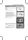
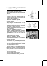
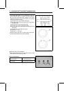
Apply liquid gasket to the mating surface [A] of the l eft
crankcase half.
Sealant - Kawasaki Bond (Liquid Gasket - Silver): 92104
-002
•
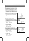
Using a suitable tool on the left crankcase to press [A]
around the hole for the crankshaft, fit the crankcase
halves together with a press on the tool.
NOTE
○
Constantly check the alignment of the two crankcase
halves, and the position of the transmission shafts, and
shift drum. The front and rear of the crankcase must be
pushed together evenly.
•
Remove the crankshaft jig from the flywheels.
•
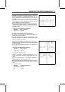
Tighten the crankcase bolts starting with the ones around
the crankshaft, and then the farther ones.
Torque - Crankcase Bolts: 8.8 N·m (0.90 kgf·m, 78 in·lb)
•
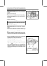
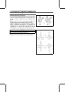
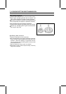
Check to see that the crankshaft, drive shaft, and output
shaft all turn freely (in the neutral position).
If the crankshaft will not turn, probably the crankshaft is
not centered; tap the appropriate end of the crankshaft
with a mallet to reposition it.
•
Spinning the output shaft, shift the transmission through
all the gears to make certain there is no binding and that
all the gears shift properly.
•
Install the parts removed in the reverse order of removal,
and refer to the appropriate chapters.
○
Replace the O-ring on the output shaft with a new one.