


83
Reference Manual
00809-0100-4444, Rev AC
Section 4: Operation
January 2015
Operation
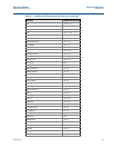
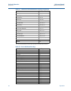
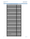
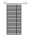
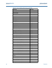
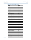
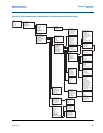
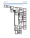
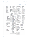
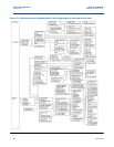
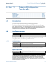
Figure 4-6. Field Communicator Traditional Menu Tree (Basic Setup and Detailed Setup)
Home
1 Device Setup
2 PV
3 PV AO
4 PV LRV
5 PV URV
Device Setup
1 Process Variables
2 Diagnostics
3 Basic Setup
4 Detailed Setup
5 Review
Basic Setup
1 Tag
2 Flow Units
3 Line Size
4 PV URV
5 PV LRV
6 Calibration Number
7 PV Damping
Flow Units
1 PV Units
2 Special Units
Detailed Setup
1 Additional Params
2 Configure Output
3 LOI Config
4 Signal Processing
5 Universal Trim
6 Device Info
7 Device Reset
Additional Params
1 Coil Drive Freq
2 Density Value
3 PV USL
4 PV LSL
5 PV Min Span
Special Units
1 Volume Unit
2 Base Volume Unit
3
Conversion Number
4 Base Time Unit
5 Flow Rate Unit
Configure Output
1 Analog Output
2 Pulse Output
3 Digital I/O
4 Reverse Flow
5 Totalizer Setup
6 Alarm Levels
7 HART Output
Analog Output
1 PV URV
2 PV LRV
3 PV Loop Current
4 PV Alarm Type
5 AO Loop Test
6 D/A Trim
7 Scaled D/A Trim
8 Alarm Level
9 AO Diagnostic Alarm
Pulse Output
1 Pulse Scaling
2 Pulse Width
3 Pulse Mode
4 Pulse Out Loop Test
Digital I/O
1 DI/DO 1
2 DO 2
3 Flow Limit 1
4 Flow Limit 2
5 Total Limit
6
Diagnostic Status
Alert
Totalizer Setup
1 Totalizer Units
2 Gross Total
3 Net Total
4 Reverse Total
5 Start Totalizer
6 Stop Totalizer
7 Reset Totalizer
AO Diagnostic Alarm
Empty Pipe
Reverse Flow
Ground/Wiring Fault
High Process Noise
Elect Temp Out of Range
Electrode Coat Limit 2
Totalizer Limit 1
Flow Limit 1
Flow Limit 2
Cont. Meter Verification
DI/DO 1
1 Configure I/O 1
2 DIO 1 Control
3 Digital Input 1
4 Digital Output 1
Flow Limit 1
1 Control 1
2 Mode 1
3 High Limit 1
4 Low Limit 1
5 Flow Limit Hysteresis
Flow Limit 2
1 Control 2
2 Mode 2
3 High Limit 2
4 Low Limit 2
5 Flow Limit Hysteresis 2
Total Limit
1 Total Control
2 Total Mode
3 Total Hi Limit
4 Total Low Limit
5 Total Limit Hysteresis
Diagnostic Status Alert
Electronics Failure
Coil Open Circuit
Empty Pipe
Reverse Flow
Ground/Wiring Fault
High Process Noise
Elect Temp Out of Range
Electrode Coat Limit 1
Electrode Coat Limit 2
Cont. Meter Verification
Coil Over Current
Sensor Electrode Saturated
Coil Power Limit
HART Output
1 Variable Mapping
2 Poll Address
3 Num Req Preams
4 Num Resp Preams
5 Burse Mode
6 Burst Option
Configure I/O 1
Input
Output
Not Available/Off
Variable Mapping
1 PV is
2 SV is
3 TV is
4 QV is
LOI Config
1 Language
2 Flowrate Display
3 Totalizer Display
4 Display Lock
5 Meter Type
6 LOI Error Mask
Signal Processing
1 Operating Mode
2 Man Config DSP
3 Coil Drive Freq
4 Low Flow Cutoff
5 PV Damping
Device Info
1 Manufacturer
2 Tag
3 Descriptor
4 Message
5 Date
6 Device ID
7 PV Sensor S/N
8 Sensor Tag
9 Write protect
Revision No.
Construction Materials
Revision No.
1 Universal Rev
2 Transmitter Rev
3 Software Rev
4 Final Assembly #
Construction Materials
1 Flange Type
2 Flange Material
3 Electrode Type
4 Electrode Material
5 Liner Material
Man Config DSP
1 Status
2 Samples
3 % Limit
4 Time Limit
Burst Option
PV
% Range/Current
Process Vars/Current
Dynamic Vars
Alarm Levels
1 Alarm Level
2 Hi Alarm
3 Hi Sat
4 Low Sat
5 Low Alarm