


35
Reference Manual
00809-0100-4444, Rev AC
Section 2: Quick Installation and Start-Up
January 2015
Quick Installation and Start-Up
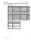
Table 2-12. Fuse Requirements
Power terminals
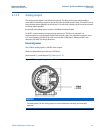
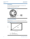
See Figure2-21 for terminal block connections.
For AC powered transmitter (90-250VAC, 50/60 Hz):
Connect AC Neutral to terminal 9 (AC N/L2) and AC Line to terminal 10 (AC/L1).
For DC powered transmitter:
Connect negative to terminal 9 (DC -) and positive to terminal 10 (DC +).
DC powered units may draw up to 1.2A.
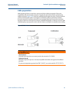
2.13 Cover jam screw
For flow meters shipped with a cover jam screw, the screw should be installed after the
instrument has been wired and powered up. Follow these steps to install the cover jam screw:
1. Verify the cover jam screw is completely threaded into the housing.
2. Install the housing cover and verify the cover is tight against the housing.
3. Using a 2.5 mm hex wrench, loosen the jam screw until it contacts the transmitter
cover.
4. Turn the jam screw an additional
1
/2 turn counterclockwise to secure the cover.
Note
Application of excessive torque may strip the threads.
5. Verify the cover cannot be removed.
Input
voltage
Fuse rating Compatible fuse
90-250VAC
rms
1 Amp, 250V, I
2
t 1.5 A
2
s
Rating, Fast Acting
Bussman AGC-1, Littelfuse 31201.5HXP
12-42VDC 3 Amp, 250V, I
2
t 14 A
2
s
Rating, Fast Acting
Bel Fuse 3AG 3-R, Littelfuse 312003P, Schurter 0034.5135