


65
Reference Manual
00809-0100-4444, Rev AC
Section 4: Operation
January 2015
Operation
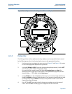
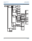
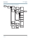
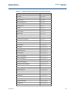
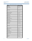
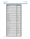
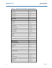
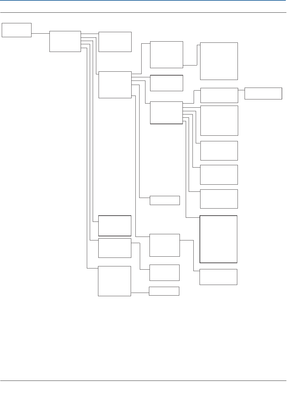
Figure 4-3. Local Operator Interface (LOI) Menu Tree (Detailed Setup)
Diagnostics
Basic Setup
Detailed Setup
More Params
Output Config
LOI Config
Sig Processing
Device Info
Coil Frequency
Proc Density
PV USL
PV LSL
PV Min Span
Analog
Pulse
DI/DO Config
Totalizer
Reverse Flow
Alarm level
HART
PV URV
PV LRV
PV AO
Alarm Type
Tes t
Alarm Level
AO Diag Alarm
Pulse Scaling
Pulse Width
Pulse Mode
Tes t
DI/O 1
DO 2
Flow Limit 1
Flow Limit 2
Total Limit
Diag Alert
Totalizer Units
Total Display
Empty Pipe
Process Noise
Ground/Wiring
Elec Coating
Elect Temp
Reverse Flow
Flow Limit 1
Flow Limit 2
Total Limit
Cont Meter Ver
DI/O 1 Control
DI 1
DO 1
Reverse Flow
Zero Flow
XMTR Fault
Empty Pipe
Flow Limit 1
Flow Limit 2
Diag Alert
Total Limit 1
Control 1
Mode 1
High Limit 1
Low Limit 1
Hysteresis
Control 2
Mode 2
High Limit 2
Low Limit 2
Hysteresis
Total Control
Total Mode
Tot Hi Limit
Tot Low Limit
Hysteresis
Elec Failure
Coil Open Ckt
Empty Pipe
Reverse Flow
Ground/Wiring
Process Noise
Elect Temp
Elec Coat 1
Elec Coat 2
Cont Meter Ver
Coil Over Curr
Sensr Elec Sat
Coil Power Lim
Variable Map
Poll Address
Req Preams
Resp Preams
Burse Mode
Burst Command
Flow Display
Total Display
Language
LOI Err Mask
Disp Auto Lock
Operating Mode
SP Config
Coil Frequency
PV Damping
Lo-Flow Cutoff
Tag
Description
Message
Device ID
PV Sensor S/N
Sensor Tag
Write Protect
Revision Num
Software Rev
Final Asmbl #
PV
SV
TV
QV
Input
Output
N/A
SP Control
Samples
% Rate
Time Limit