


190
Reference Manual
00809-0100-4444, Rev AC
Appendix A: Implementing a Universal Transmitter
January 2015
Implementing a Universal Transmitter
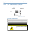
A.7 Kent Veriflux VTC sensor
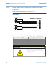
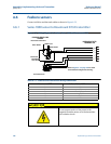
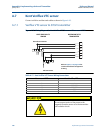
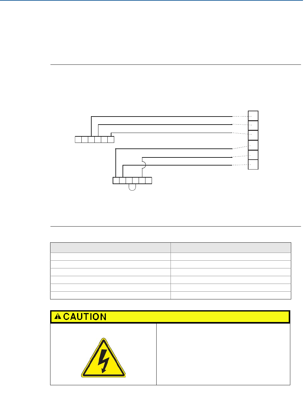
Connect coil drive and electrode cables as shown in Figure A-16.
A.7.1 Veriflux VTC sensor to 8732 transmitter
Figure A-16. Wiring Diagram for Kent Veriflux VTC Sensor and Rosemount 8732
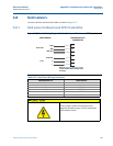
Table A-17. Kent Veriflux VTC Sensor Wiring Connections
Rosemount 8732 Kent Veriflux VTC sensors
1 2
2 1
3 SCR OUT
17 SCR OUT
18 SIG1
19 SIG2
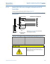
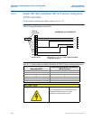
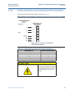
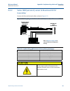
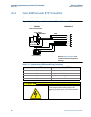
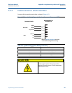
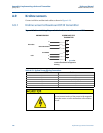
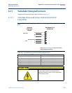
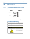
Do not connect mains or line power to the
magnetic flowtube sensor or to the transmitter
coil excitation circuit.
1
2
17
18
19
3
Electrode Connections
Coil Connections
ROSEMOUNT 8732
TRANSMITTER
KENT VERIFLUX VTC
SENSOR
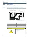
1SCR OUT
2
3 SIG 1
4 SIG 2
5
6
1
2–
5+
6 SCR OUT
Refer to Figure A-1 on page 174 for
actual terminal block configuration
drawing.