


194
Reference Manual
00809-0100-4444, Rev AC
Appendix A: Implementing a Universal Transmitter
January 2015
Implementing a Universal Transmitter
A.10.2 Taylor sensor to Rosemount 8732 transmitter
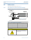
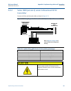
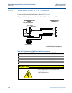
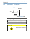
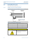
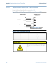
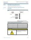
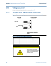
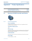
Connect coil drive and electrode cables as shown in Figure A-20.
Figure A-20. Generic Wiring Diagram for Taylor Sensors and Rosemount 8732
Table A-21. Taylor Sensor Wiring Connections
Rosemount 8732 Taylor sensors
1 Black
2 White
3 Green
17 S1 and S2
18 E1
19 E2
Do not connect mains or line power to the magnetic
flowtube sensor or to the transmitter coil excitation
circuit.
Electrodes
Coils
Green
ROSEMOUNT 8732
TRANSMITTER
TAYLOR SENSORS
White
Black
E2
E1
S1 and S2
Refer to Figure A-1 on page 174 for actual
terminal block configuration drawing.
1
2
17
18
19
3