


151
Reference Manual
00809-0100-4444, Rev AC
Section 9: Troubleshooting
January 2015
Tro ubles hooting
Apply power to the magnetic flowmeter system before making the following transmitter
checks:
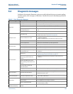
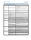
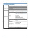
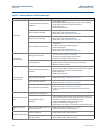
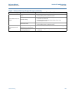
1. Check for an active error message or status alert. Refer to 9.4 Diagnostic messages.
2. Verify the correct sensor calibration number is entered in the transmitter. The
calibration number is listed on the sensor nameplate.
3. Verify the correct sensor line size is entered in the transmitter. The line size value is
listed on the sensor nameplate.
4. Verify the analog range of the transmitter matches the analog range in the control
system.
5. Verify the forced analog output and forced pulse output of the transmitter produces
the correct output at the control system.
6. If desired, use a Rosemount 8714D to verify the transmitter calibration.
9.3.2 Sensor
Be sure that power to magnetic flowmeter system is removed before beginning the following
sensor checks:
1. Record the sensor model number and serial number.
2. Visually inspect the sensor for any damage including inside the remote junction box, if
applicable.
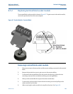
3. For horizontal flow installations, ensure that the electrodes remain covered by process
fluid. For vertical or inclined installations, ensure that the process fluid is flowing up into
the sensor to keep the electrodes covered by process fluid.
4. Verify the flow arrow is pointing in the same direction as forward flow.
5. Ensure the grounding straps on the sensor are connected to grounding rings, lining
protectors, or the adjacent pipe flanges. Improper grounding will cause erratic
operation of the system. Sensors with a ground electrode will not require the
grounding straps to be connected.