


21
Reference Manual
00809-0100-4444, Rev AC
Section 2: Quick Installation and Start-Up
January 2015
Quick Installation and Start-Up
To order an Alignment Spacer Kit (qty 3 spacers) use p/n 08711-3211-xxxx along with the Dash
no. above.
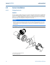
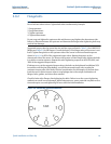
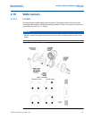
2.10.3 Flange bolts
Wafer sensors require threaded studs. See Figure 2-8 on page 15 for torque sequence. Always
check for leaks at the flanges after tightening the flange bolts. All sensors require a second
tightening 24 hours after initial flange bolt tightening.
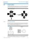
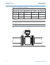
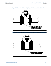
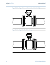
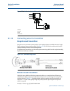
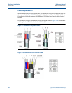
2.11 Process reference connection
Figure 2-10 through Figure 2-13 illustrate process reference connections only. Earth safety
ground is also required as part of the installation but is not shown in the figures. Follow national,
local, and plant electrical codes for safety ground.
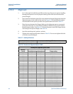
Use Tab le 2- 10 to determine which process reference option to follow for proper installation.
DD30 3 80 EN 1092-1 - PN10/16/25/40
DD40 4 100 EN 1092-1 - PN25/40
DD60 6 150 EN 1092-1 - PN25/40
DD80 8 200 EN 1092-1 - PN40
RA80 8 200 AS40871-PN16
RC20 2 50 AS40871-PN21/35
RC30 3 80 AS40871-PN21/35
RC40 4 100 AS40871-PN21/35
RC60 6 150 AS40871-PN21/35
RC80 8 200 AS40871-PN21/35
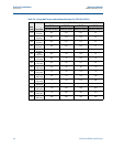
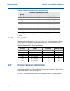
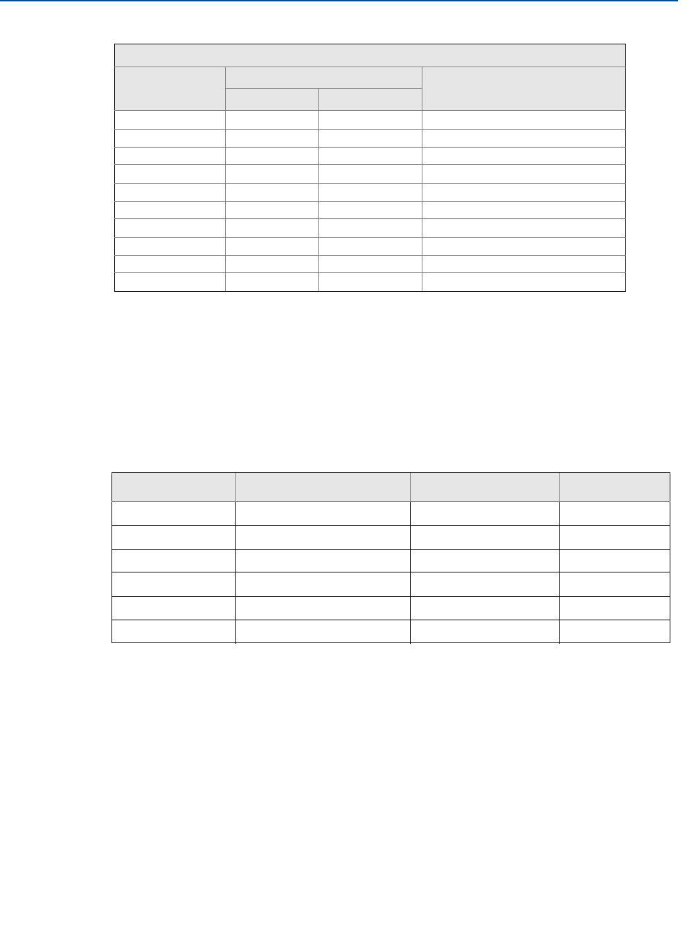
Table 2-9. Rosemount 8711 Torque Specifications
Size code Line size Pound-feet Newton-meter
015 1.5-in. (40 mm) 15 20
020 2-in. (50 mm) 25 34
030 3-in. (80 mm) 40 54
040 4-in. (100 mm) 30 41
060 6-in. (150 mm) 50 68
080 8-in. (200 mm) 70 95
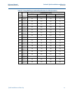
Table 2-8. Rosemount Alignment Spacer Table (continued)
Rosemount alignment spacer table
Dash no.
(-xxxx)
Line size
Flange rating(in) (mm)