


15
Reference Manual
00809-0100-4444, Rev AC
Section 2: Quick Installation and Start-Up
January 2015
Quick Installation and Start-Up
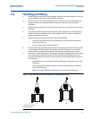
2.9.2 Flange bolts
Note
Do not bolt one side at a time. Tighten both sides simultaneously. Example:
1. Snug upstream
2. Snug downstream
3. Tighten upstream
4. Tighten downstream
Do not snug and tighten the upstream side and then snug and tighten the downstream side.
Failure to alternate between the upstream and downstream flanges when tightening bolts may
result in liner damage.
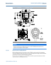
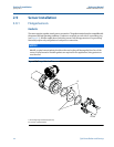
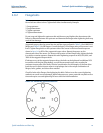
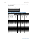
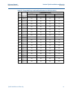
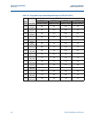
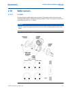
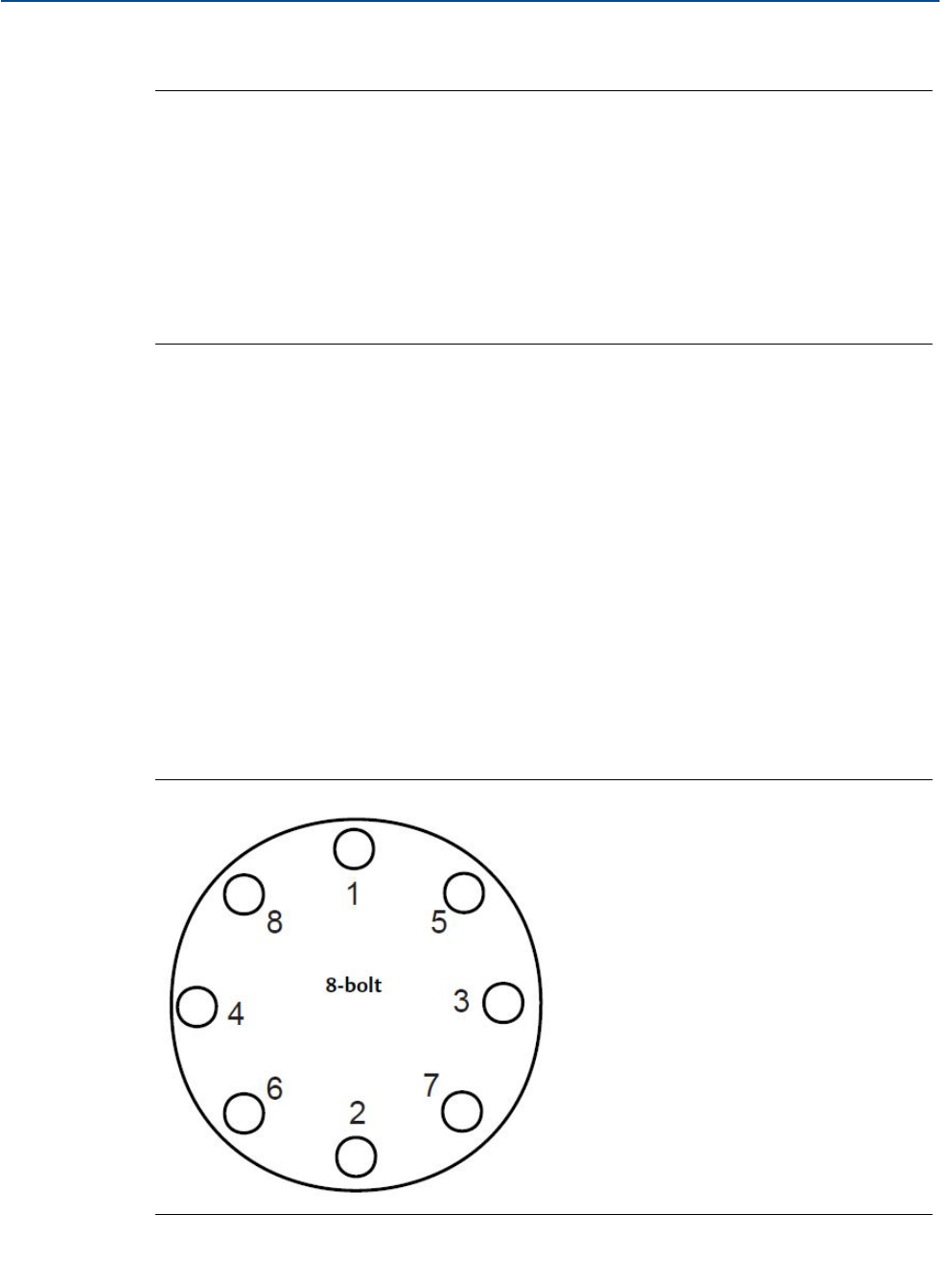
Suggested torque values by sensor line size and liner type are listed in Ta ble 2- 4 for ASME B16.5
flanges and Ta ble 2 -5 for EN flanges. Consult the factory if the flange rating of the sensor is not
listed. Tighten flange bolts on the upstream side of the sensor in the incremental sequence
shown in
Figure 2-8 to 20% of the suggested torque values. Repeat the process on the
downstream side of the sensor. For sensors with greater or fewer flange bolts, tighten the bolts
in a similar crosswise sequence. Repeat this entire tightening sequence at 40%, 60%, 80%, and
100% of the suggested torque values.
If leakage occurs at the suggested torque values, the bolts can be tightened in additional 10%
increments until the joint stops leaking, or until the measured torque value reaches the
maximum torque value of the bolts. Practical consideration for the integrity of the liner often
leads the user to distinct torque values to stop leakage due to the unique combinations of
flanges, bolts, gaskets, and sensor liner material.
Check for leaks at the flanges after tightening the bolts. Failure to use the correct tightening
methods can result in severe damage. While under pressure, sensor materials may deform over
time and require a second tightening 24 hours after the initial installation.
Figure 2-8. Flange Bolt Torquing Sequence