


169
Reference Manual
00809-0100-4444, Rev AC
Section 9: Troubleshooting
January 2015
Tro ubles hooting
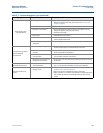
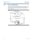
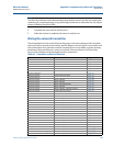
9.6.3 Installed sensor tests
If a problem with an installed sensor is identified, refer to Table 9-8 on page 168 to assist in trou-
bleshooting the sensor. Disconnect or turn off power to the transmitter before performing any
of the sensor tests. Always check the operation of test equipment before each test.
If possible, take all readings from feed-through pins in the sensor adapter. If the pins in the
sensor adapter are inaccessible, take measurements at the sensor terminal block or through
remote cabling as close to the sensor as possible. Readings taken through remote cabling that is
more than 100 feet (30 meters) in length may provide incorrect or inconclusive information and
should be avoided.
The expected values in the test below assume the measurements have been taken directly at
the pins.
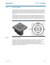
To test the sensor, a multimeter capable of measuring conductance in nanoSiemens is
preferred. Conductance is the reciprocal of resistance.
Or:
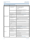
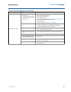
Table 9-8. Sensor Tests and Expected Values
Test
Sensor
location
Required
equipment
Measuring at
connections Expected value Potential cause Corrective action
A. Sensor coil
Installed or
uninstalled
Multimeter 1 and 2 = R
• Open or shorted
coil
•Remove and
replace sensor
B. Shields to
case
Installed or
uninstalled
Multimeter
17 and 3
3 and case
ground
17 and case
ground
•Moisture in
terminal block
• Leaky electrode
• Process behind
liner
• Clean terminal
block
•Remove sensor
C. Coil to coil
shield
Installed or
uninstalled
Multimeter
1 and 3
2 and 3
(< 1nS)
(< 1nS)
• Process behind
liner
• Leaky electrode
•Moisture in
terminal block
•Remove sensor
and dry
• Clean terminal
block
• Confirm with
sensor coil test
D. Electrode to
electrode
shield
Installed
LCR (Set to
Resistance
and 120 Hz)
18 and 17 = R
1
19 and 17 = R
2
R
1
and R
2
should be stable
•Unstable R
1
or R
2
values confirm
coated electrode
•Shorted
electrode
•Electrode not in
contact with
process
• Empty pipe
• Low conductivity
• Leaky electrode
•Process
reference
ground not
connected
properly
•Remove coating
from sensor wall
•Use bullet-nose
electrodes
•Repeat
measurement
•Remove sensor
and complete
tests in Ta bl e 9- 9
• Connect process
reference ground
per 2.11 Process
reference
connection
E. Electrode to
Electrode
Installed
LCR (set to
resistance
and 120 Hz)
18 and 19
Should be stable and same
relative magnitude of R
1
and
R
2
from Test D
• See Test D above • See Test D above
2 R18
0.3
R
1
R–
2
300