8
Reference Manual
00809-0100-4444, Rev AC
Section 2: Installation
January 2015
Quick Installation and Startup
Be sure to identify any additional options and configurations that apply to the installation. Keep
a list of these options for consideration during the installation and configuration procedures.
2.5.3 Mechanical considerations
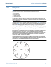
The mounting site for the 8732EM Transmitter should provide enough room for secure
mounting, easy access to conduit entries, full opening of the transmitter covers, and easy
readability of the Local Operator Interface (LOI) screen (if equipped).
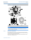
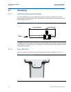
For remote mount transmitter (8732EMRxxx) installations a mounting bracket is provided for
use on a 2-inch pipe or a flat surface (see Figure 2-1).
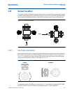
Rotate integral mount transmitter housing
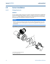
The transmitter housing can be rotated on the sensor in 90-degree increments by removing the
four mounting screws on the bottom of the housing. Do not rotate the housing more than
180 degrees in any one direction. Prior to tightening, be sure the mating surfaces are clean, the
O-ring is seated in the groove, and there is no gap between the housing and the sensor.
NOTICE
To prevent switch damage, use a non-metallic tool to move switch positions.
NOTICE
If the 8732EM is mounted separately from the sensor, it may not be subject to limitations
that might apply to the sensor.


