


43
Reference Manual
00809-0100-4444, Rev AC
Section 3: Advanced Installation Details
January 2015
Advanced Installation Details
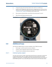
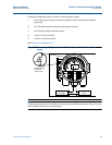
6. Change the setting of the desired switches with a small, non-metallic tool.
7. Replace the LOI if applicable, and the electronics compartment cover. If the cover has a
cover jam screw, this must be tightened to comply with installation requirements. See
“Cover jam screw” on page 35 for details on the cover jam screw.
8. Return power to the transmitter and verify the flow measurement is correct.
9. Return the control loop to automatic control.
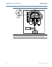
Figure 3-1. Rosemount 8732EM Electronics Stack and Hardware Switches
3.4 Additional loops
There are three additional loop connections available on the 8732EM Transmitter:
Pulse output - used for external or remote totalization.
Channel 1 can be configured as discrete input or discrete output.
Channel 2 can be configured as discrete output only.
3.4.1 Connect pulse output
The pulse output function provides a galvanically isolated frequency signal that is proportional
to the flow through the sensor. The signal is typically used in conjunction with an external
totalizer or control system. The default position of the internal/external pulse power switch is in
the EXTERNAL position. The user-selectable power switch is located on the electronics board.