


10
Reference Manual
00809-0100-4444, Rev AC
Section 2: Installation
January 2015
Quick Installation and Startup
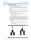
2.5.5 Environmental considerations
To ensure maximum transmitter life, avoid extreme temperatures and excessive vibration.
Typical problem areas include the following:
High-vibration lines with integrally mounted transmitters
Tropical/desert installations in direct sunlight
Outdoor installations in arctic climates
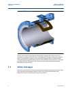
Remote mounted transmitters may be installed in the control room to protect the electronics
from the harsh environment and to provide easy access for configuration or service.
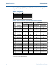
Table 2-2. Electrical Data
Rosemount 8732EM Flow Transmitter
Power input 90 - 250VAC, 0.45A, 40VA
12 - 42VDC, 1.2A, 15W
Pulsed circuit Internally powered (Active): Outputs up to 12VDC, 12.1mA, 73mW
Externally powered (Passive): Input up to 28VDC, 100mA, 1W
4-20mA output
circuit
Internally Powered (Active): Outputs up to 25mA, 24VDC, 600mW
Externally Powered (Passive): Input up to 25mA, 30VDC, 750mW
Um 250V
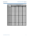
Coil excitation
output
500mA, 40V max, 9W max
Rosemount 8705-M and 8711-M/L Flowtube
(1)
Coil excitation
input
500mA, 40V max, 20W max
Electrode circuit 5V, 200uA, 1mW
(1) Provided by the transmitter