


7
Reference Manual
00809-0100-4444, Rev AC
Section 2: Quick Installation and Start-Up
January 2015
Quick Installation and Start-Up
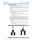
2.4 Pre-installation
Before installing the Rosemount 8732EM Magnetic Flowmeter Transmitter, there are several
pre-installation steps that should be completed to make the installation process easier:
Identify the options and configurations that apply to your application
Set the hardware switches if necessary
Consider mechanical, electrical, and environmental requirements
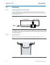
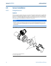
2.5 Installation procedures
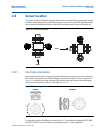
2.5.1 Transmitter installation
Installation of the Rosemount Magnetic Flowmeter includes both detailed mechanical and
electrical installation procedures.
2.5.2 Identify options and configurations
The typical installation of the 8732EM includes a device power connection, a 4–20mA output
connection, and sensor coil and electrode connections. Other applications may require one or
more of the following configurations or options:
Pulse Output
Discrete Output
Discrete Input
HART
®
Multidrop Configuration
Hardware switches
The 8732EM electronics stack is equipped with user-selectable hardware switches. These
switches set the Alarm Mode, Internal/External Analog Power, Internal/External Pulse Power, and
Transmitter Security. The standard configuration for these switches when shipped from the
factory are as follows:
In most cases, it will not be necessary to change the setting of the hardware switches. If the
switch settings need to be changed, follow the steps outlined in “Changing hardware switch
settings” on page 42).
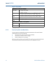
Table 2-1. Standard Switch Configuration
Alarm Mode High
Internal/External Analog Power
(1)
(1) For electronics with intrinsically safe analog and pulse outputs, the power
must be provided externally. In this configuration, these two hardware
switches are not provided.
Internal
Internal/External Pulse Power
(1)
External
Transmitter Security
Off