


11
Reference Manual
00809-0100-4444, Rev AC
Section 2: Quick Installation and Start-Up
January 2015
Quick Installation and Start-Up
2.6 Handling and lifting
Handle all parts carefully to prevent damage. Whenever possible, transport the system
to the installation site in the original shipping container.
PTFE-lined sensors are shipped with end covers that protect it from both mechanical
damage and normal unrestrained distortion. Remove the end covers just before
installation.
Keep the shipping plugs in the conduit connections until you are ready to connect and
seal them.
The sensor should be supported by the pipeline. Pipe supports are recommended on
both the inlet and outlet sides of the sensor pipeline. There should be no additional
support attached to the sensor.
Additional safety recommendations for mechanical handling:
- Use proper PPE (Personal Protection Equipment should include safety glasses
and steel toed shoes).
- Do not drop the device from any height.
Do not lift the meter by holding the electronics housing or junction box.The sensor liner
is vulnerable to handling damage. Never place anything through the sensor for the
purpose of lifting or gaining leverage. Liner damage can render the sensor useless.
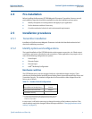
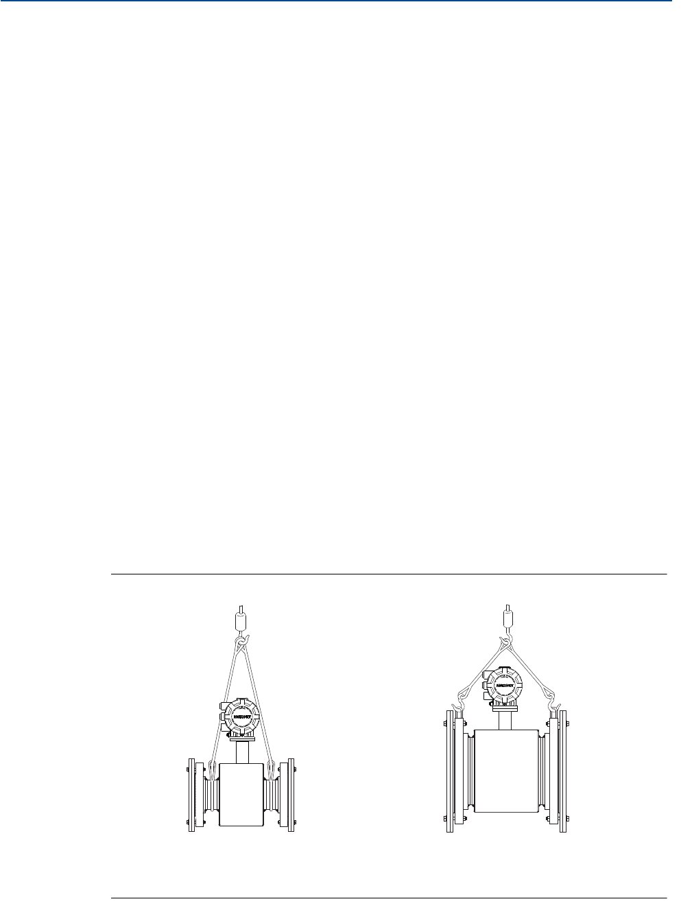
If provided, use the lifting lugs on each flange to handle the Magnetic Flowmeter when
it is transported and lowered into place at the installation site. If lifting lugs are not
provided, the Magnetic Flowmeter must be supported with a lifting sling on each side
of the housing.
- Standard Pressure 3 through 36-inch Flanged Magnetic Flowmeters come with
lifting lugs.
- High Pressure (above 600#) 1 through 24-inch Flanged Magnetic Flowmeters
come with lifting lugs.
- Wafers and Sanitary Magnetic Flowmeters do not come with lifting lugs.
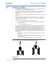
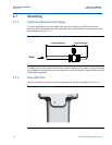
Figure 2-2. Rosemount 8705 Sensor Support for Handling and Lifting
A. Without Lifting Lugs
B. With Lifting Lugs
AB